
Adjustable hinge joint support

a technology of hinge joint support and adjustment, which is applied in the field of orthopaedic support, can solve the problems of not maximizing efficiency and healing, and the appropriate hinge action cannot be smoothly carried out, and achieves the effect of facilitating the positioning and securement of the hinges

Active Publication Date: 2007-05-15
CAERUS CORP
View PDF29 Cites 56 Cited by
  • Summary
  • Abstract
  • Description
  • Claims
  • Application Information

AI Technical Summary

Benefits of technology

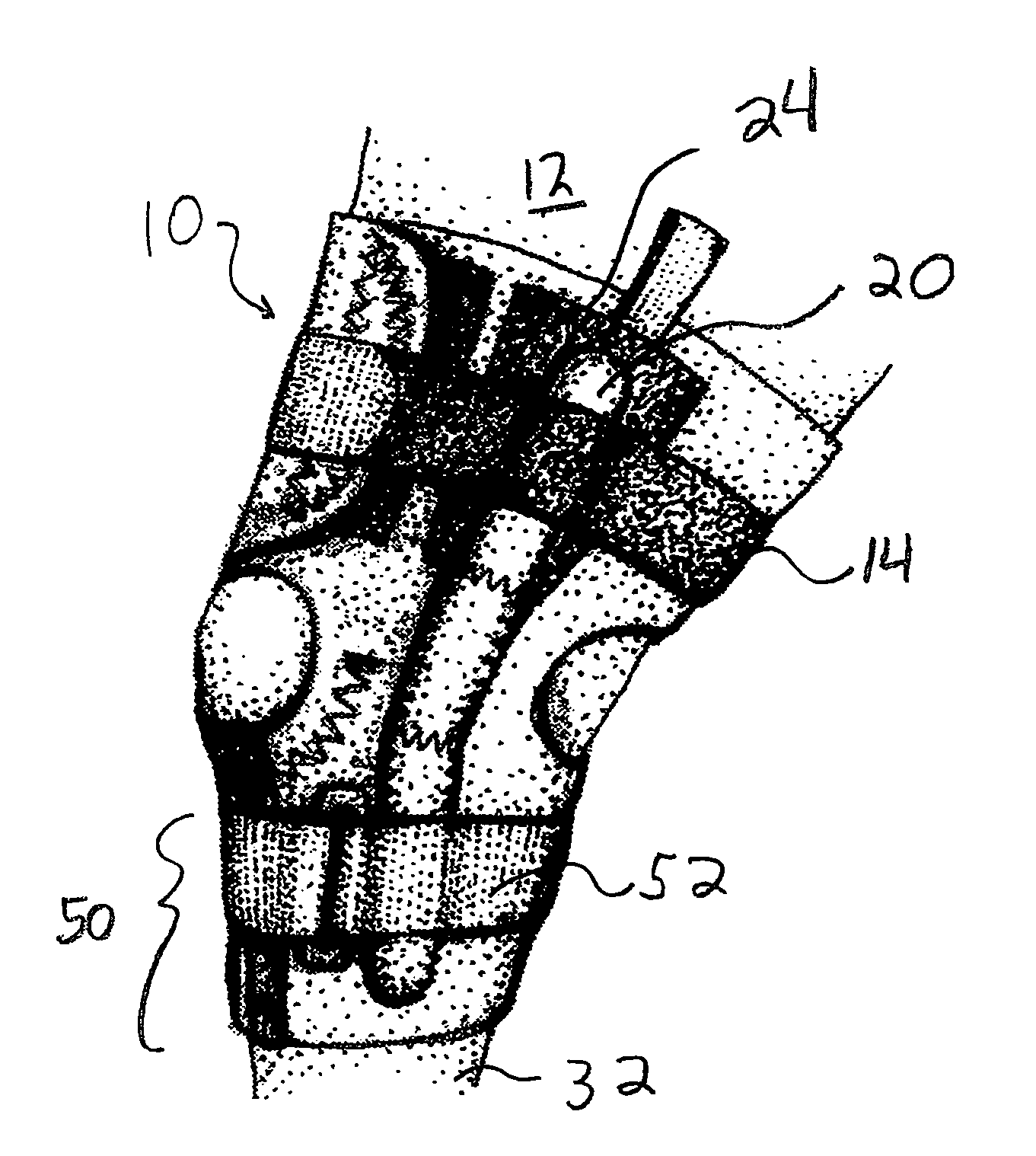
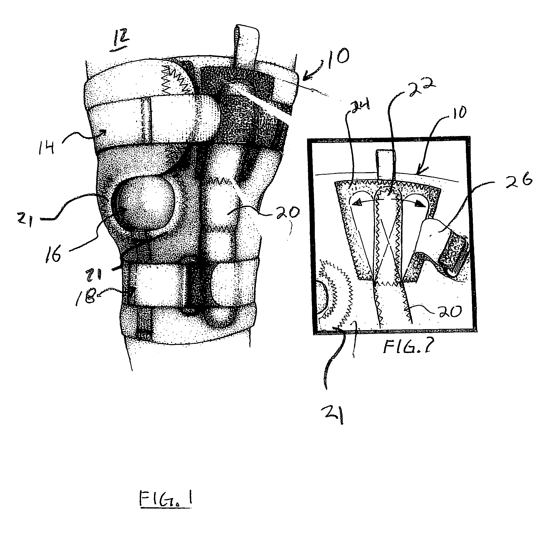
[0009]The present invention relates generally to orthopedic supports having hinge elements associated therewith. More particularly, one aspect of the invention includes an orthopedic support facilitating better fit for legs of varying shape, including the cone-shaped leg and the positioning of the support around the thigh. In one aspect of the present invention, hinges disposed for positioning above the patella have unique hook and pile adjustments to fit larger or smaller thighs (from child sizes to adult sizes) and allow proper balanced support on opposite sides of the knee. In another aspect a posterior elastic segment on velcro straps prevent any tourniquet effect. Moreover, the present invention may, in one embodiment, provide a universal right or left leg applicability with removable, adjustable half-horseshoe buttress.
[0012]In still another aspect of the present invention, a spiral stay may be used so that as the knee is bent by a user, the stay encourages the present invention to return to a neutral position after each movement. In this manner, as the knee is returned to a neutral position such that pressure exerted on the knee neither pushes or pulls the tissues of the knee apart.
[0013]In yet another aspect of the present invention, hook and pile inter-engagement is used to facilitate the positioning and securement of the hinges in the most appropriate location relative to the knee.
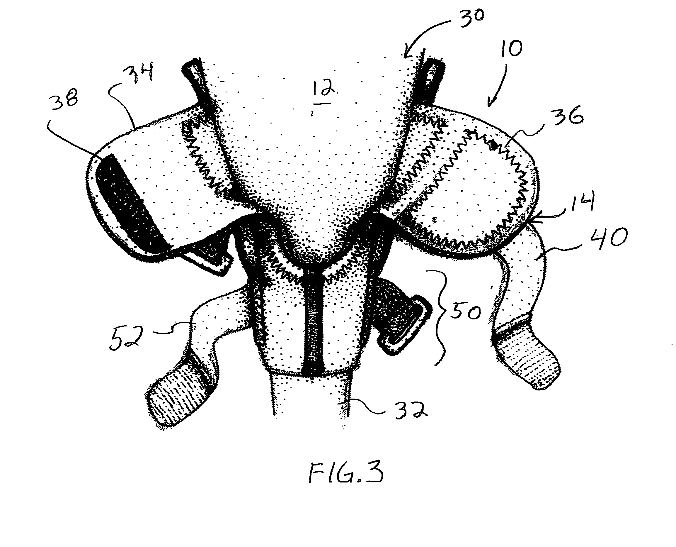
[0014]And yet a further aspect of the present invention, a hinged knee support is provided with a patient friendly configuration having a closed bottom section for covering the calf of the patient and an upper region that may be open and adjusted to the appropriate size for accommodating a variation in the size of the thigh of the user. The hinged knee further incorporates the adjustable hinge feature as described above therein facilitating structural support of patients having a wide variation of certain anatomical regions thereof.

Problems solved by technology

If the hinges are not diametrically opposed one to the other, the appropriate hinge action cannot smoothly occur.
Such a problem is contrary to the purpose of the orthopedic support and will not maximize efficiency and healing.

Method used


Image

  • Adjustable hinge joint support
  • Adjustable hinge joint support
  • Adjustable hinge joint support

Examples


Embodiment Construction

[0023]It has been discovered that many commercial braces do not fit certain sizes and shapes in the most appropriate manner. This is particularly true of legs with large thighs and smaller calf regions. These leg shapes are referred to herein as “cone-shaped” legs and illustrated in certain ones of the following drawings. Further, the present invention may be adapted to fit the leg shapes of both children and adults.

[0024]Referring now to FIG. 1, there is shown an adjustable hinged knee support 10 constructed in accordance with the principles of the present invention. The knee support 10 facilitates a better fit for users having large thighs or “cone-shaped” legs 12. An adjustable upper fastener assembly 14 accommodates the various thigh sizes. As shown in FIG. 1, a large patella opening 16 (or alternatively, a large popliteal opening) is also provided for added comfort. On opposite sides of opening 16 are removable, adjustable half-horseshoe buttress' 21 for comfort and support (se...


PUM


Abstract

A brace for supporting the knee of the wearer. The brace has an adjustable support mechanism for accommodating a variety of leg shapes. The hinge portion of the brace is adjustable so that there is proper balanced support on opposite sides of the knee. Furthermore, the brace is universal in applicability and may be used on either the right or left leg.

Description

CROSS-REFERENCE[0001]This application claims priority from and incorporates the entire disclosure of U.S. Provisional Patent Application No. 60 / 361,901 filed Feb. 28, 2002.BACKGROUND[0002]1. Technical Field of the Invention[0003]The present invention relates to orthopedic supports and, more particularly, but not by way of limitation, to an orthopedic support for a knee having a hinge that may be adjustably positioned for anatomically correct support of knees and legs of varying sizes and shapes.[0004]2. History of Related Art[0005]It is common in the Sports Medicine Industry to utilize orthopedic supports for various body parts subject to injury. The most common support areas include the knees, elbows, and ankles. Often injuries to these areas of the body can be treated by the utilization of the appropriate orthopedic support. In the event surgery, rehabilitation is sometimes augmented by the utilization of such supports.[0006]The design of orthopedic supports has changed considerab...

Claims


Application Information

Patent Timeline
Patent Type & Authority Patents(United States)
IPC IPC(8): A61F5/00
CPCA61F5/0109A61F5/0123A61F2005/0176
Inventor SCOTT, JOHN
Owner CAERUS CORP
Learn More