
Method for active engine stop of a hybrid electric vehicle

a hybrid electric vehicle and active technology, applied in the direction of electric control, machines/engines, speed sensing governors, etc., can solve the problems of difficult packaging, affecting operator and passenger feel, perceived vehicle performance, etc., to improve smoothness, improve the durability of the driveline, and improve the effect of noise, vibration and harshness performan

Active Publication Date: 2007-05-15
GM GLOBAL TECH OPERATIONS LLC
View PDF7 Cites 36 Cited by
  • Summary
  • Abstract
  • Description
  • Claims
  • Application Information

AI Technical Summary

Benefits of technology

[0010]This method provides the benefit of improving durability of the driveline and improving smoothness during the engine stop by limiting the amount of vibration energy dissipated into the powertrain and vehicle chassis. The invention is particularly advantageous in that it may be used with many different types and sizes of engines having many different base idle speeds. It permits a plug and play implementation of different engines without the need to tailor the powertrain system to obtain acceptable noise, vibration and harshness performance.

Problems solved by technology

However, long springs can encounter problems in buckling and are very difficult to package.
A key difference between certain EVT transmissions and other transmissions is that the engine is continuously coupled through a spring damper to the transmission and its large inertias.
These large inertias produce significant vibrational energy as the engine and transmission pass through a resonant frequency associated with the engine speed (e.g. the resonance speed of an compression engine / spring damper / transmission system is approximately 400 rpm for a six cylinder engine which permits sufficient attenuation by idle speed (i.e., 600 rpm and higher)), thereby affecting operator and passenger feel and perceived vehicle performance.

Method used


Image

  • Method for active engine stop of a hybrid electric vehicle
  • Method for active engine stop of a hybrid electric vehicle
  • Method for active engine stop of a hybrid electric vehicle

Examples


Embodiment Construction

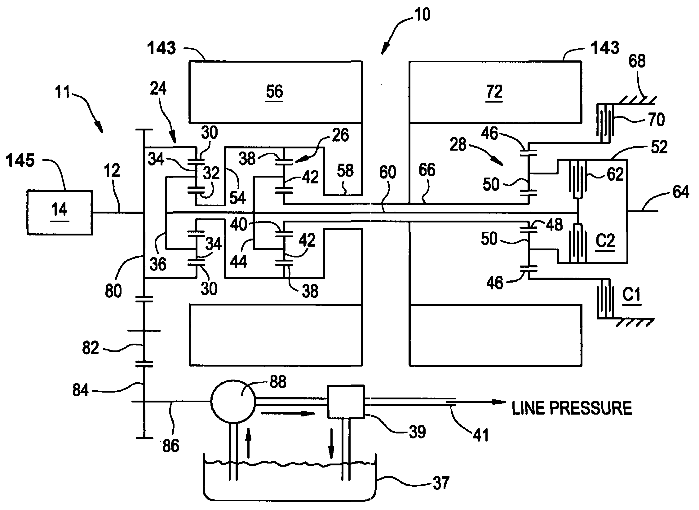
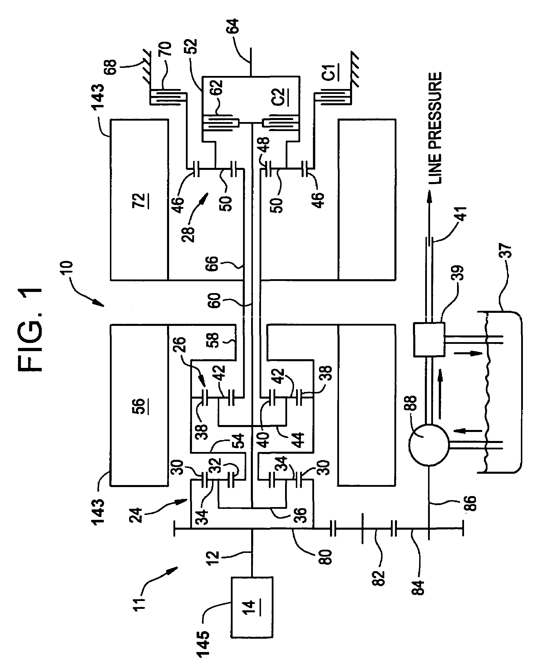
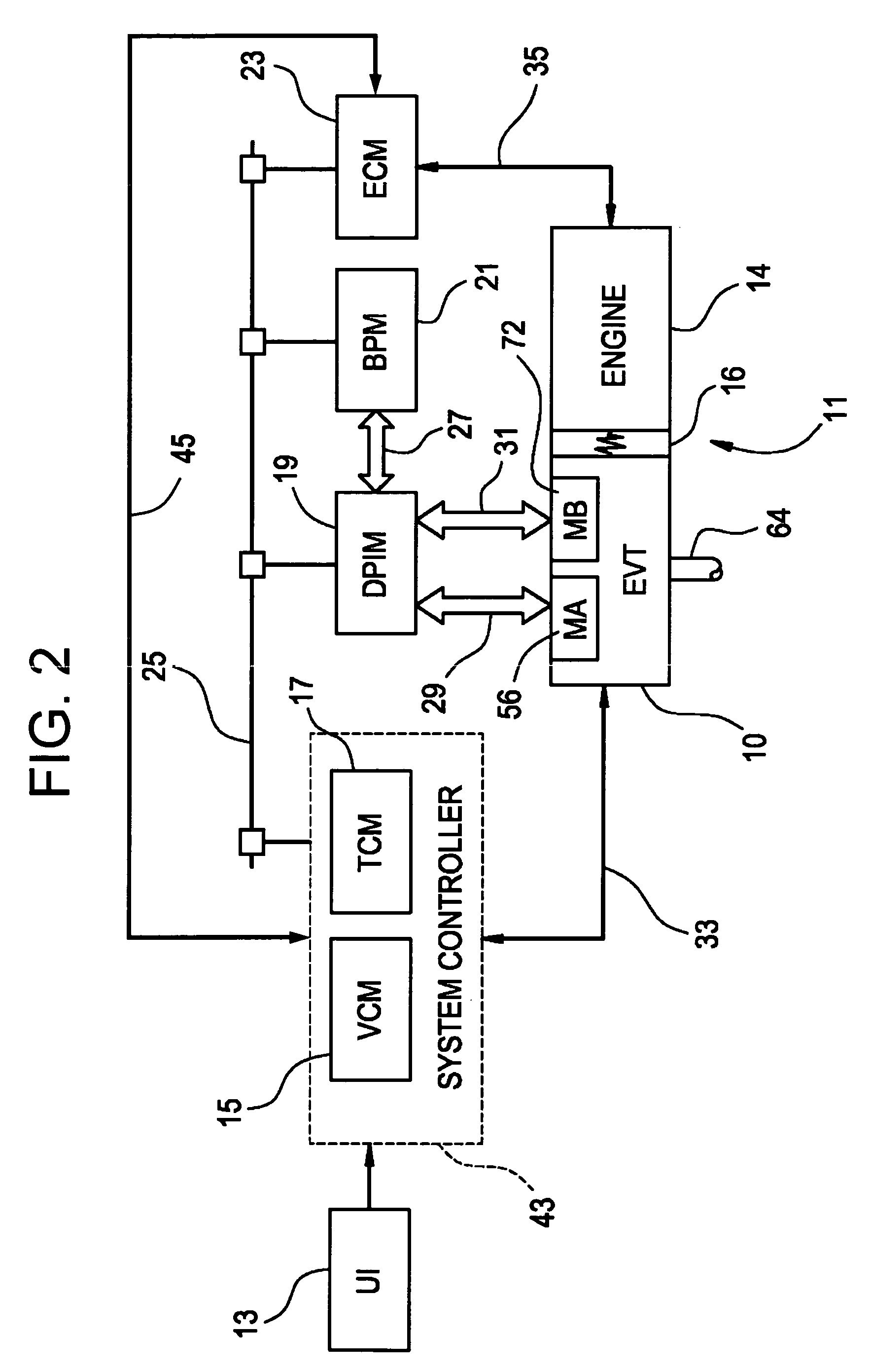
[0021]With reference first to FIGS. 1 and 2, a vehicular powertrain is generally designated 11. Included in the powertrain 11 is one representative form of a multi-mode, compound-split, electrically variable transmission (EVT) particularly suited for implementing the controls of the present invention and designated generally by the numeral 10 in FIGS. 1 and 2. With particular reference, then, to those FIGS., the EVT 10 has an input member 12 that may be in the nature of a shaft which may be directly driven by an engine 14 or, as shown in FIG. 2, a transient torque damper 16 may be incorporated between the output member of the engine 14 and the input member of the EVT 10. The transient torque damper 16 may incorporated, or be employed in conjunction with, a torque transfer device (not shown) to permit selective engagement of the engine 14 with the EVT 10, but it must be understood that such a torque transfer device is not utilized to change, or control, the mode in which the EVT 10 o...


PUM


Abstract

A method for providing an active engine stop of the engine of a hybrid electric vehicle. The method utilizes the electric machine to oppose and rapidly stop the rotation of the engine at a controlled rate. The method includes the calculation of an input speed reduction trajectory using the engine speed when the active engine stop request is made and a predetermined speed reduction interval. The speed reduction interval is less than a time from the active stop request to the shutoff command to the electric machine The method provides rapid deceleration of the engine, particularly through the powertrain resonance speed, reducing the amount of vibration energy dissipated through the powertrain and chassis. The method removes the electric machine torques from the engine prior to achieving zero engine speed in order to avoid imparting a negative engine speed or counter-rotation of the engine.

Description

TECHNICAL FIELD[0001]The present invention generally relates to a method of operating a hybrid electric vehicle. More particularly, the method relates to an operating mode for controlling a vehicle powertrain system of a hybrid electric vehicle. Most particularly, the method relates to an operating mode for providing an active engine stop for a hybrid electric vehicle.BACKGROUND OF THE INVENTION[0002]An HEV is a vehicle that has a propulsion system that consists of at least one electric motor or electric machine in combination with at least one other power source. Typically, the other power source is a gasoline or diesel engine. There are various types of HEVs depending on how the electric motor(s) and other power source(s) are combined with one another in order to provide propulsion for the vehicle, including series, parallel and compound HEVs.[0003]Various hybrid powertrain architectures are known for managing the input and output torques of various propulsion systems in HEVs, mos...

Claims


Application Information

Patent Timeline
Patent Type & Authority Patents(United States)
IPC IPC(8): B60K1/02B60K1/00B60W10/06B60W10/08B60W20/00F02D31/00F02D41/04
CPCB60K6/445B60W10/08B60W20/102F02D41/042B60W10/06Y10T477/24B60W2710/0616B60W2710/0661F02D31/001F02D2250/24Y02T10/6286Y02T10/48Y02T10/6239Y10T477/23Y10T477/26Y10T477/865B60W20/11Y02T10/40Y02T10/62
Inventor SAH, JY-JEN F.HUBBARD, GREGORY A.BENNETT, ADAM C.STEINMETZ, TODD M.FOSTER, MICHAEL D.
Owner GM GLOBAL TECH OPERATIONS LLC
Learn More