Exhaust treatment diagnostic using a temperature sensor

a temperature sensor and exhaust treatment technology, applied in the direction of machines/engines, electrical control, mechanical equipment, etc., can solve the problem of insufficient amount of dosing agent to properly treat the exhaus

Active Publication Date: 2007-05-15
GM GLOBAL TECH OPERATIONS LLC
View PDF7 Cites 16 Cited by
  • Summary
  • Abstract
  • Description
  • Claims
  • Application Information

AI Technical Summary

Problems solved by technology

A faulty injector or an insufficient dosing agent supply would result in an inadequate amount of dosing agent to properly treat the exhaust.

Method used


Image

  • Exhaust treatment diagnostic using a temperature sensor
  • Exhaust treatment diagnostic using a temperature sensor
  • Exhaust treatment diagnostic using a temperature sensor

Examples


Embodiment Construction

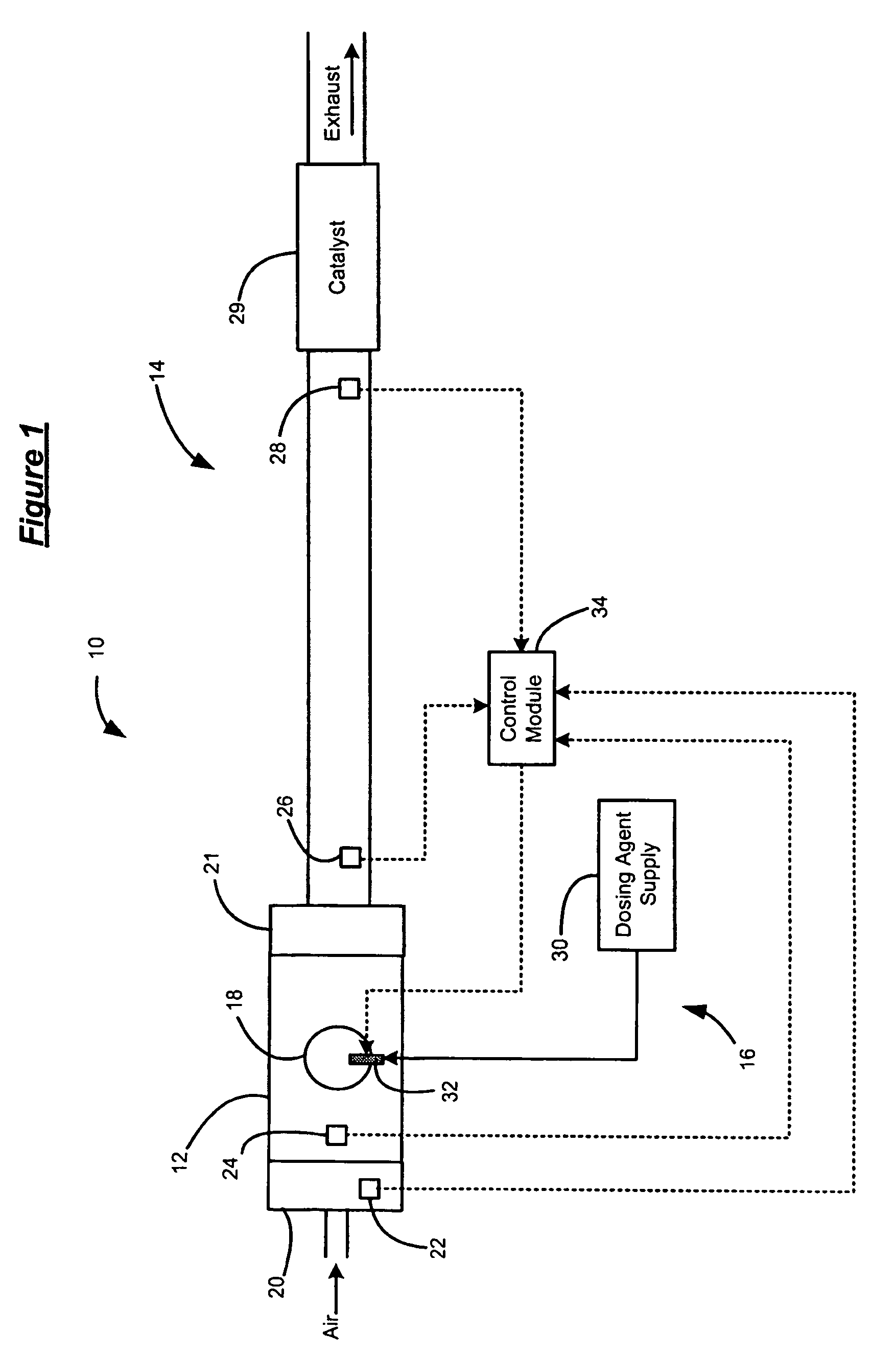
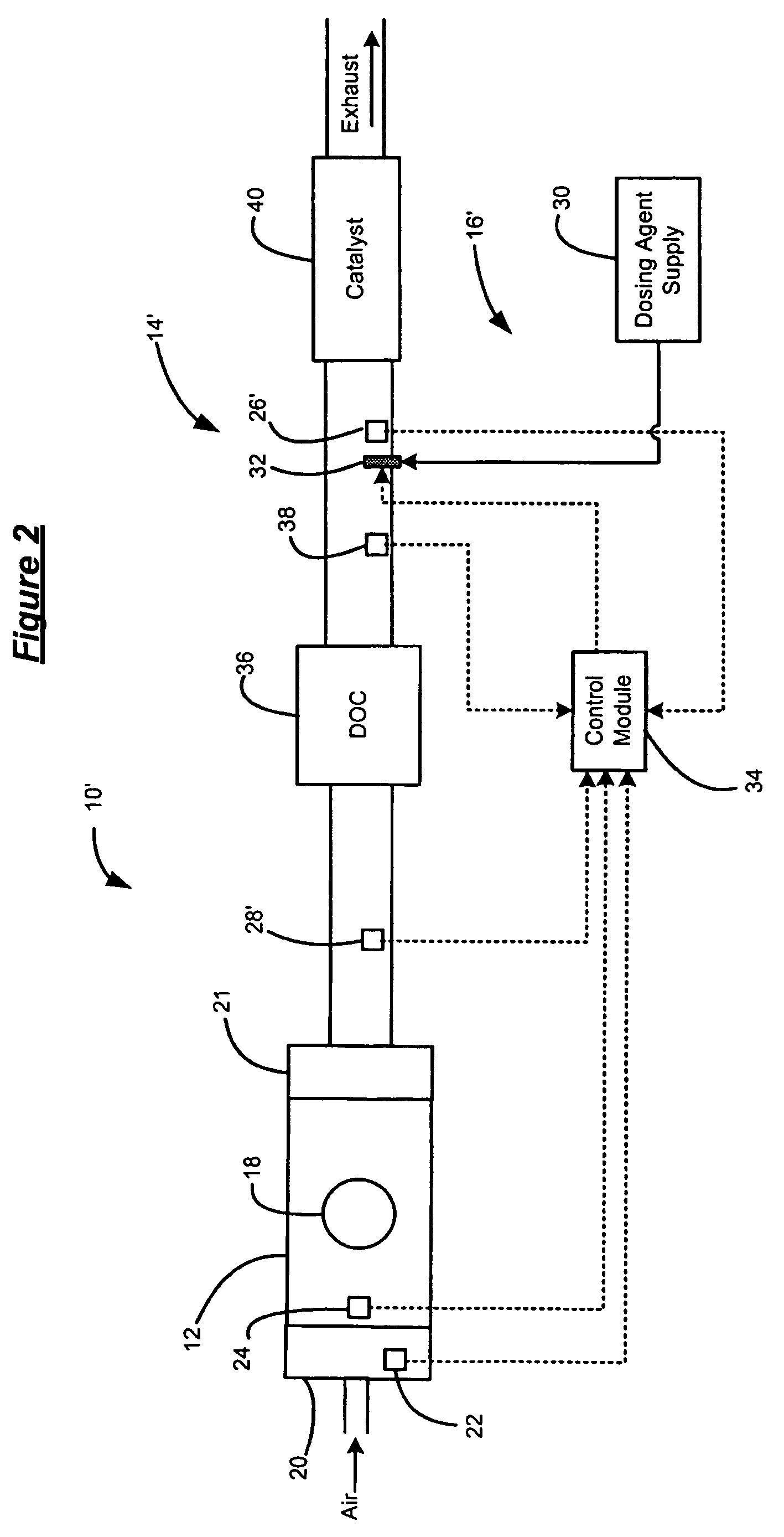
[0019]The following description of the preferred embodiment is merely exemplary in nature and is in no way intended to limit the invention, its application, or uses. For purposes of clarity, the same reference numbers will be used in the drawings to identify similar elements. As used herein, the term module refers to an application specific integrated circuit (ASIC), an electronic circuit, a processor (shared, dedicated, or group) and memory that execute one or more software or firmware programs, a combinational logic circuit, or other suitable components that provide the described functionality.

[0020]Referring now to FIG. 1, an engine system 10 is schematically illustrated. The engine system 10 includes an engine 12, an exhaust system 14 and a dosing system 16. The engine 12 includes a cylinder 18, an intake manifold 20, a manifold absolute pressure (MAP) sensor 22 and an engine speed sensor 24. Air flows into the engine 12 through the intake manifold 20 and is combusted with fuel ...


PUM


Abstract

A method of monitoring operation of a dosing system for treating exhaust of an engine includes monitoring a downstream temperature of an exhaust downstream of the dosing system and injecting a dosing agent. A control module determines a temperature differential threshold based on an amount of dosing agent injected and calculates a temperature differential. The control module further evaluates operation of the dosing system based on the temperature differential and the temperature differential threshold.

Description

FIELD OF THE INVENTION[0001]The present invention relates to vehicle exhaust systems, and more particularly to treating exhaust of an engine.BACKGROUND OF THE INVENTION[0002]Engine operation includes a combustion process and an exhaust process. During the combustion process, an air / fuel mixture is combusted within cylinders to drive pistons (not shown). A vehicle engine produces exhaust as a result from the combustion of air and fuel. During the exhaust process, exhaust is released from the cylinders into the exhaust system. The exhaust contains Nitrous Oxide (NOx) and Carbon Monoxide (CO) that is treated before the exhaust is released from the vehicle.[0003]An exhaust treatment system is used to reduce the amount of emissions (e.g., NOx) in the exhaust. A control module monitors engine operation and emissions levels and a dosing system injects a reducing agent into the exhaust upstream from a catalyst. The treated exhaust reacts with the catalyst and a chemical reaction occurs that...

Claims


Application Information

Patent Timeline
Patent Type & Authority Patents(United States)
IPC IPC(8): F01N3/00
CPCF01N3/0253F01N3/035F01N3/2033F01N9/00F01N11/002F01N13/009F02D41/0235F02D41/1446F02D41/146F01N13/0097F01N2550/05Y02T10/26Y02T10/47F01N2560/026Y02T10/12Y02T10/40
Inventor BROWN, DAVID B.PARATORE, JR., MICHAEL J.VIOLA, MICHAEL B.
Owner GM GLOBAL TECH OPERATIONS LLC
Why Eureka
Try Eureka