
Rear projector

a projector and rear-facing technology, applied in the field of rear-facing projectors, can solve the problems of high elastic deformation rate, and achieve the effects of reliably preventing dust from passing through the cell, preventing dust entry, and preventing dust deposition

Inactive Publication Date: 2007-05-08
SEIKO EPSON CORP
View PDF7 Cites 5 Cited by
  • Summary
  • Abstract
  • Description
  • Claims
  • Application Information

AI Technical Summary

Benefits of technology

[0007]The present invention has been made in view of the above described point for improvement, and a main object of the present invention is to provide a rear projector capable of preventing entry of dust.
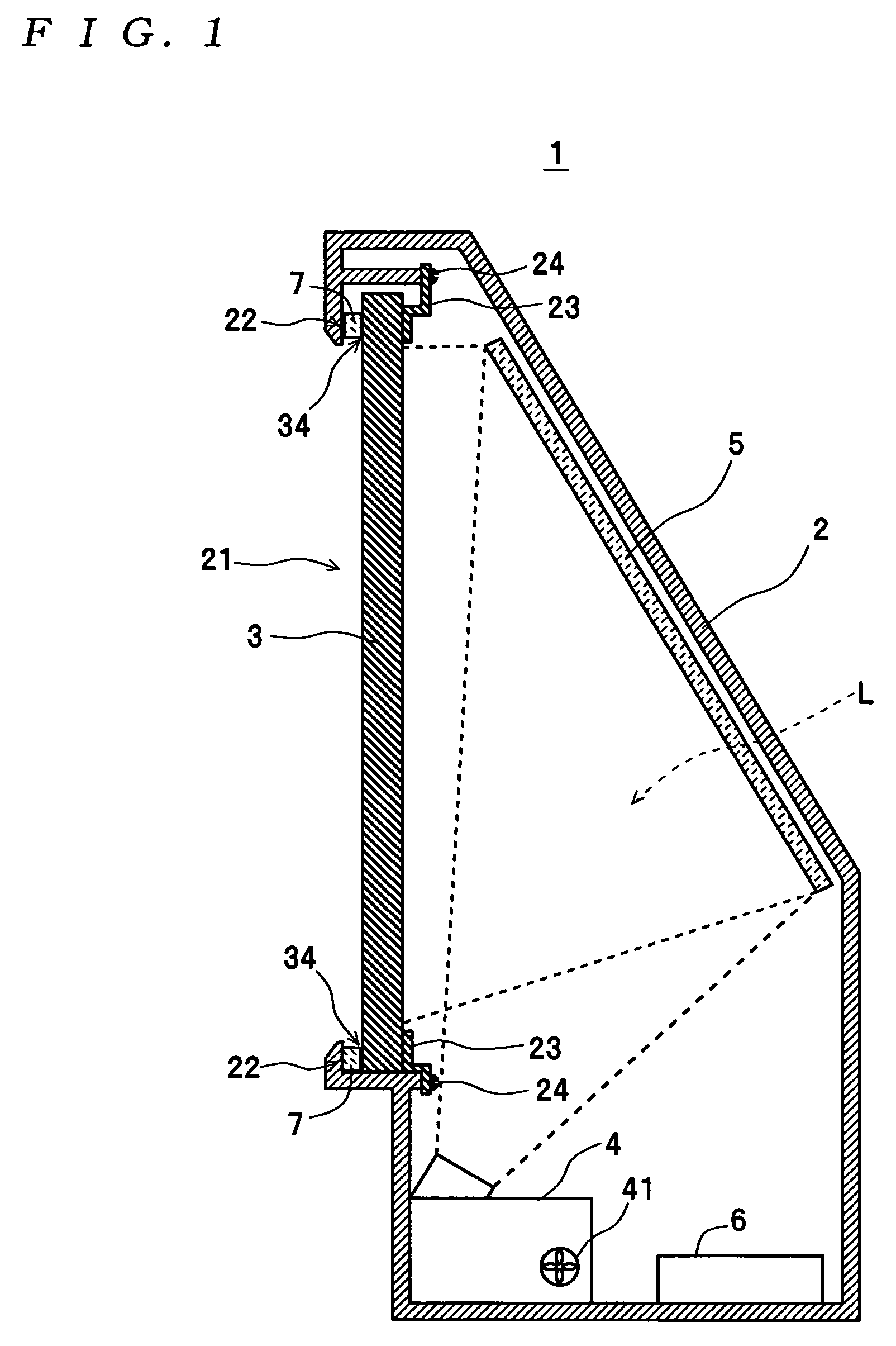
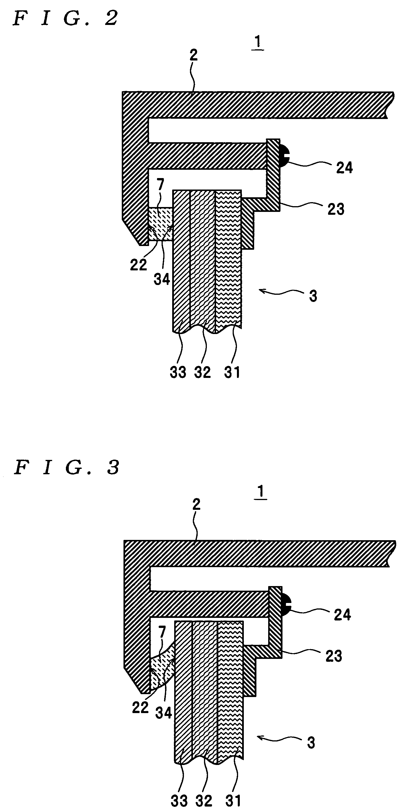
[0009]According to this rear projector, the screen panel is attached to the front side of the housing the dust-proofing elastic member between the periphery of the screen panel and the opening edge portion of the opening of the housing. Therefore, even when the screen panel thermally expands, a gap cannot be formed between the screen panel and the housing, which makes it possible to reliably prevent entry of dust into the housing, and hence prevent deposition of dust on the projection mechanism and the rear surface of the screen panel.
[0010]Preferably, the elastic member is formed of a closed-cell expanded resin. According to this preferred embodiment, since cells are separate from each other within the closed-cell expanded resin, it is possible to reliably prevent dust from passing through the cells into the inside of the housing. Further, the closed-cell expanded resin has a high elastic deformation rate, so that even when the screen panel largely expands, the closed-cell expanded resin is held in intimate contact with the periphery of the screen panel and the opening edge portion of the housing. Consequently, even when the screen panel largely expands, it is possible to reliably prevent separation of the elastic member from the periphery of the screen panel and the opening edge portion of the housing, thereby preventing a gap from being formed between the periphery of the screen panel and the elastic member or between the opening edge portion of the housing and the elastic member.

Problems solved by technology

Further, the closed-cell expanded resin has a high elastic deformation rate, so that even when the screen panel largely expands, the closed-cell expanded resin is held in intimate contact with the periphery of the screen panel and the opening edge portion of the housing.

Method used


Image

  • Rear projector
  • Rear projector
  • Rear projector

Examples


Embodiment Construction

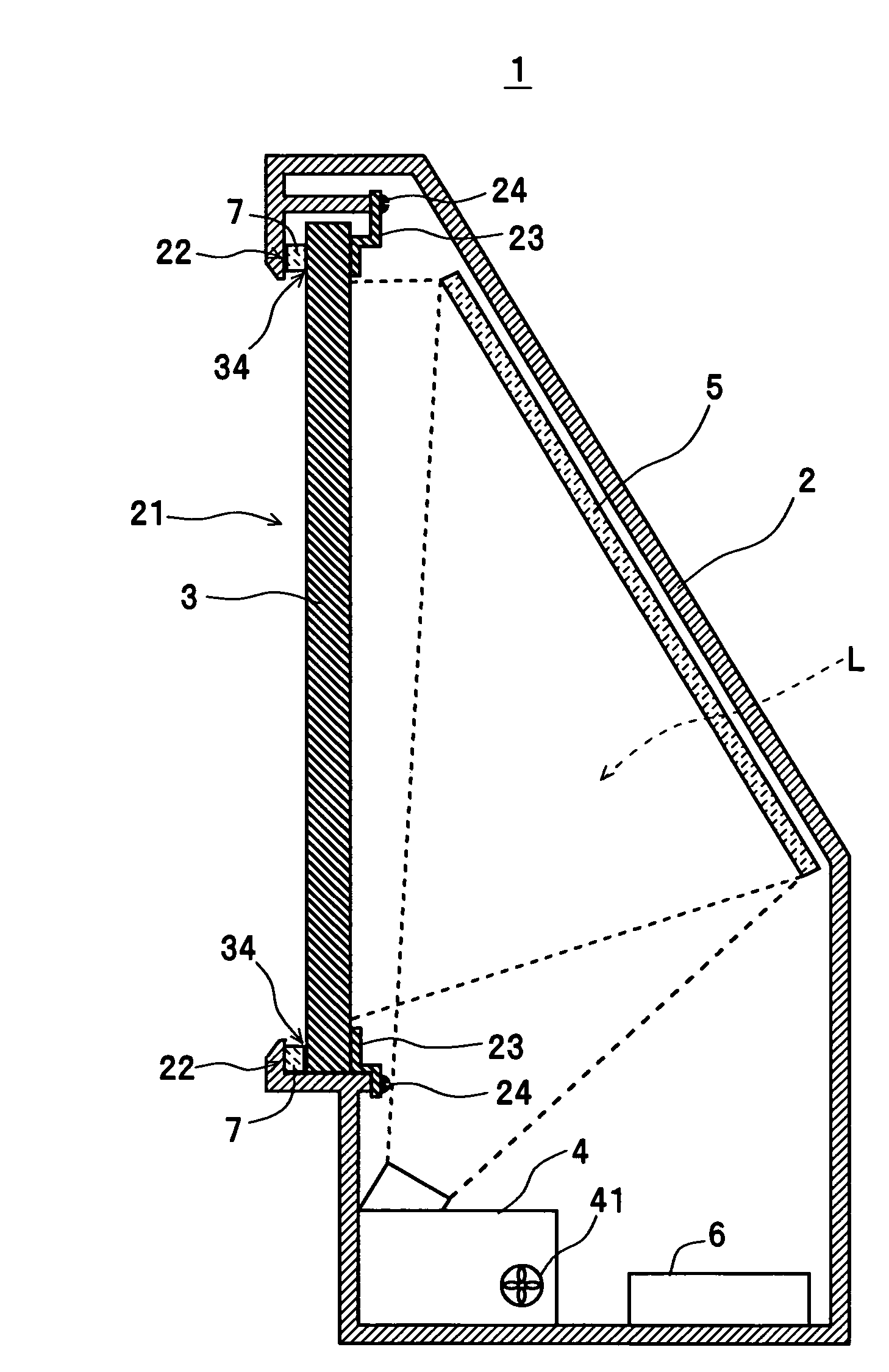
[0016]The invention will now be described with reference to the accompanying drawings showing a preferred embodiment thereof. First, a description will be given of the arrangement of a rear projection television (hereinafter also simply referred to as “the television”) 1. As shown in FIG. 1, the television 1 as an example of the rear projector of the present invention is comprised of a cabinet (housing) 2, a screen panel 3, a projector unit 4, a mirror 5, a control unit 6, and a sealing member 7. The television 1 is capable of displaying various kinds of images, such as TV(television) pictures. The cabinet 2 is in the form of a box having a sloped surface on its rear side and a front side thereof formed with an opening 21 having a rectangular shape as viewed from the front of the cabinet 2.

[0017]The screen panel 3 is formed to have a rectangular shape, as viewed from the front of the cabinet 2, which is slightly larger in size than the opening 21. The screen panel 3 is attached to a...


PUM


Abstract

There is provided a rear projector capable of preventing entry of dust. A cabinet of the rear projector has a front side thereof formed with an opening. A screen panel slightly larger in size than the opening is attached to the front side of the cabinet such that the opening edge portion of the opening of the cabinet and the periphery of the screen panel are opposed to each other. The screen panel receives projection light projected from behind for image display, and thereby displays an image thereon. A projector unit is disposed within the cabinet, for projecting the projection light. A dust-proofing sealing member is disposed between the periphery of the screen panel and the opening edge portion, the screen panel is attached to the housing.

Description

BACKGROUND OF THE INVENTION[0001]1 Field of the Invention[0002]The present invention relates to a rear projector which displays an image on a screen panel by projected projection light from behind the screen panel.[0003]2 Description of the Related Art[0004]With proliferation of digital broadcasting and widespread use of digital AV (audio-visual) devices in recent years, there is an increasing demand for displays capable of displaying images of high quality on a large screen. As a display of this kind, the present assignee has already proposed a rear projector which displays images by the rear projection method, in Japanese Laid-Open Patent Publication (Kokai) No. 2002-296678. In the rear projector, part of which is shown in FIG. 4, a projection device disposed within a housing 13 modulates incident light (white light) from a light source lamp into projection light for image display, based on image information inputted from an external image information output device, and projects t...

Claims


Application Information

Patent Timeline
IPC IPC(8): G03B21/56G03B21/22G03B21/10G03B3/00G03B21/14H04N5/64H04N5/74
CPCG03B21/14G03B21/10F16L41/021F16L55/07
Inventor KATO, SHIGEKIYAMADA, HARUYOSHISEKI, SHIGEYUKI
Owner SEIKO EPSON CORP
Learn More