
Method for tracking targets with hyper-spectral data

a hyper-spectral data and target technology, applied in the field of remote sensing and remote imaging, can solve the problems of gap and delay in tracking information, the inability to distinguish the energy between the two targets, and the limitations of the h-pmht algorithm, and achieve the effect of improving the low signal-to-noise ratio (snr) tracking

Active Publication Date: 2007-05-01
US SEC NAVY THE
View PDF2 Cites 12 Cited by
  • Summary
  • Abstract
  • Description
  • Claims
  • Application Information

AI Technical Summary

Benefits of technology

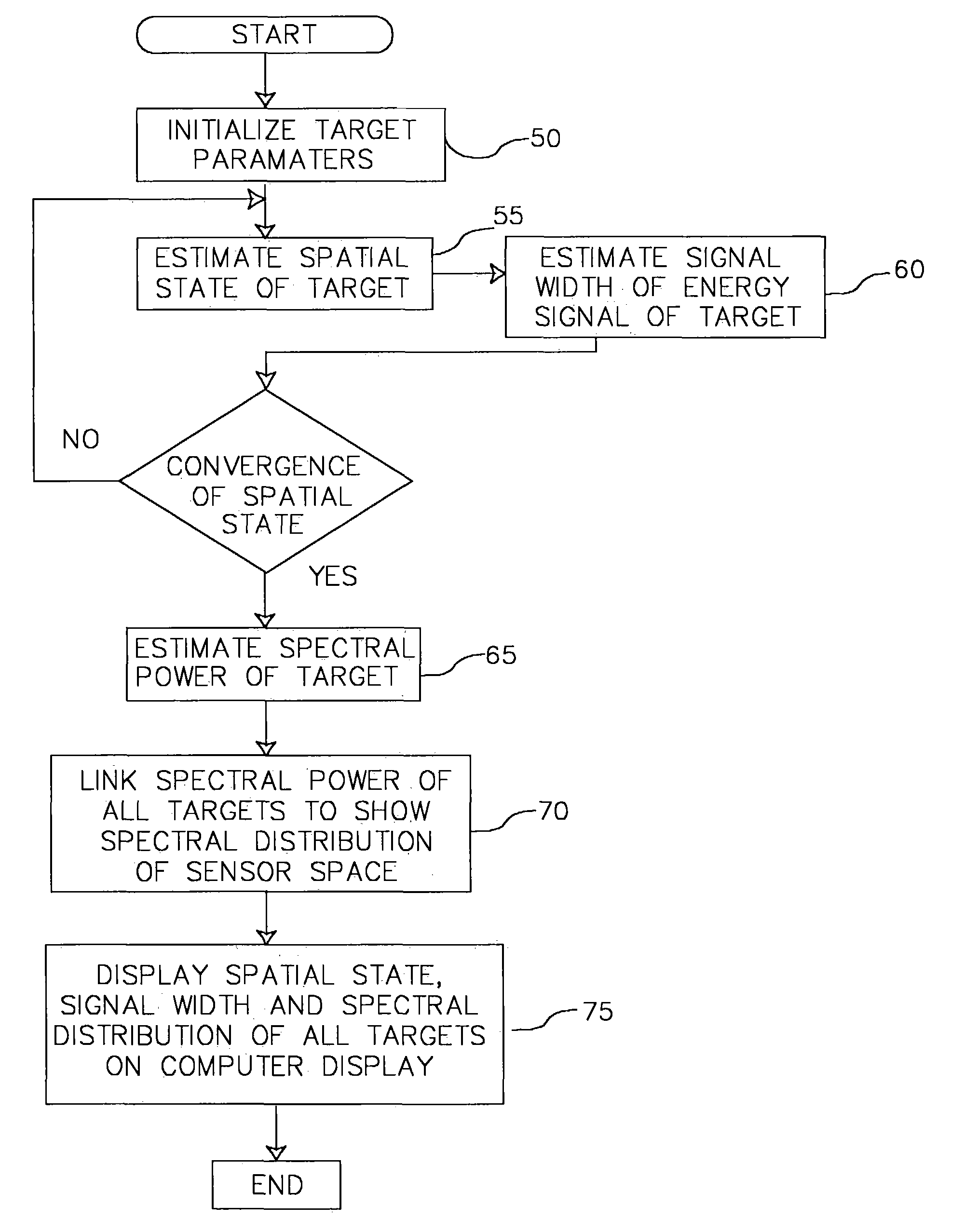
[0012]The present invention modifies H-PMHT by using a non-parametric spectral characterization of the energy intensity of the target that is assumed known. The use of such a spectral template enhances low signal to noise ratio (SNR) tracking and allows discrimination of spectrally distinct sources as they cross in the spatial domain. The track solutions from previous batches are used to estimate the (non-parametric) spectral characterization that is used to initiate the generation of the updated solutions as new data is received and processed.
[0013]The present invention provides a mechanism for separating the observed hyperspectral energy into the hyperspectral energy for each source (including noise) using the known spectral characteristics for each source. Completely general spectral density functions are handled via the use of non-parametric methods. In the alternative, the source spectrum is estimated in a non-parametric fashion based on an initial track, allowing the algorithm to adapt to the source spectrum in situ.

Problems solved by technology

The H-PMHT algorithm has its limitations.
For example, in situations where more than one target is being tracked and the targets cross paths, the intensity of the energy signals of the targets merge, making it impossible to distinguish the energy between the two targets.
In such a situation, the targets must be reacquired by the sensors after they have crossed resulting in a gap and delay in tracking information.
This method does not, however, address the problem of distinguishing between and identifying the targets before, during and after they have crossed.
There is currently no reliable method by which targets can be consistently tracked and distinguished as they cross paths.

Method used


Image

  • Method for tracking targets with hyper-spectral data
  • Method for tracking targets with hyper-spectral data
  • Method for tracking targets with hyper-spectral data

Examples


Embodiment Construction

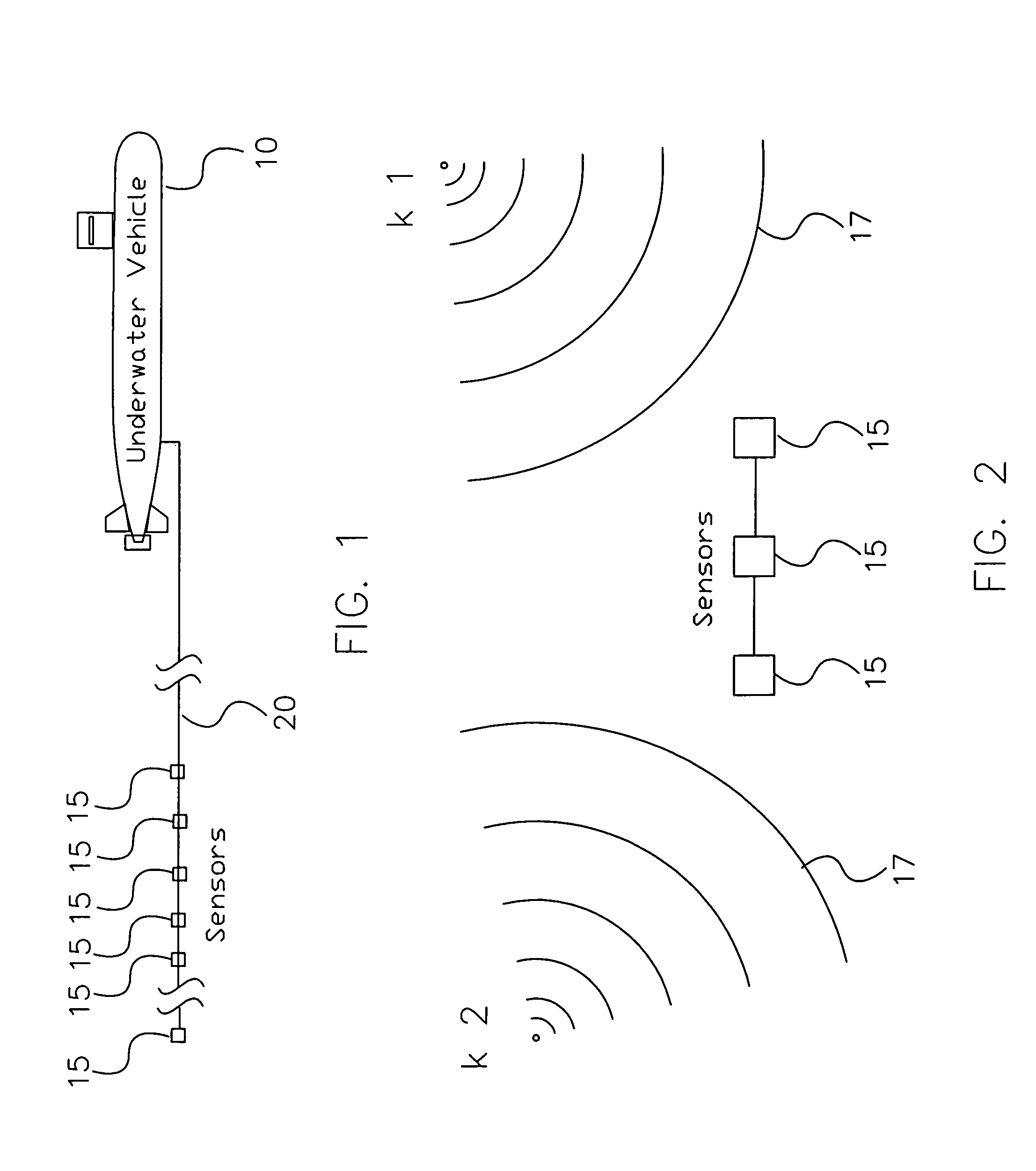
[0019]Referring now to FIG. 1 there is shown an underwater vehicle 10 towing an array of sensors 15 arranged on a cable 20. The sensors 15 are of a type known by those skilled in the art of signal processing such as hydrophones. The sensors 15 are capable of detecting energy signals and their intensities from different directions as illustrated in FIG. 2, which shows two vessels labeled k1 and k2 and the energy signals 17 emanating from the vessels. The sensor data from each sensor 15 is transmitted along cable 20 to data processors (not shown) within underwater vehicle 10. The data processors take the raw sensor data and create a data cube 25 as illustrated in FIG. 3. Each such data cube 25 is a collection of smaller cubes referred to as sensor cells 30 which correspond to the processed sensor data generated by the sensors 15. Each sensor cell 30 contains spatial measurements along the x-axis 31, spectral measurements along the y-axis 32 and time measurements along the t-axis 33. T...


PUM


Abstract

In the present invention, the histogram model used in H-PMHT is extended to treat the problem of tracking using hyper-spectral data. Completely general spectral density functions are handled via the use of non-parametric methods. The present invention is not restricted to derivations based on knowledge of the spectral character of the source being tracked. The source spectrum can be estimated in a non-parametric fashion based on an initial track, and this allows the invention to adapt to the source spectrum in situ. The resulting method has improved crossing track performance on sources that have some degree of spectral distinction and will perform no worse than regular H-PMHT on sources that have identical spectral densities.

Description

STATEMENT OF GOVERNMENT INTEREST[0001]The invention described herein may be manufactured and used by or for the Government of the United States of America for governmental purposes without the payment of any royalties thereon or therefore.CROSS REFERENCE TO OTHER PATENT APPLICATIONS[0002]Not applicable.BACKGROUND OF THE INVENTION[0003](1) Field of the Invention[0004]The present invention relates to remote sensing and remote imaging, and more specifically to a method for processing hyper-spectral remote sensor data for the purpose of displaying the spatial tracks of energy sources in multi-spectral images corresponding to the sensor data.[0005](2) Description of the Prior Art[0006]Remote sensing of the energy signals of a moving vehicle or energy source for the purposes of tracking the vehicle or energy source has often been accomplished by measuring the intensity of the energy signals with sensors specifically designed to detect energy intensity. In remote sensing applications the s...

Claims


Application Information

Patent Timeline
IPC IPC(8): G06K9/00
CPCG01S3/8006G06K9/0057G01S15/66G06F2218/22
Inventor GRAHAM, MARCUS L.LUGINBUHI, TOD E.STREIT, ROY L.WALSH, MICHAEL J.
Owner US SEC NAVY THE
Learn More