Twisted waveguide and wireless device
a waveguide and wireless technology, applied in coupling devices, electrical devices, antennas, etc., can solve the problems of narrowing the utilizable frequency range, reducing the utilisation frequency range, and the manufacturing process of the window must be complicated, so as to reduce the overall cost, reduce the manufacturing cost, and wide the frequency range characteristic
- Summary
- Abstract
- Description
- Claims
- Application Information
AI Technical Summary
Benefits of technology
Problems solved by technology
Method used
Image
Examples
first embodiment
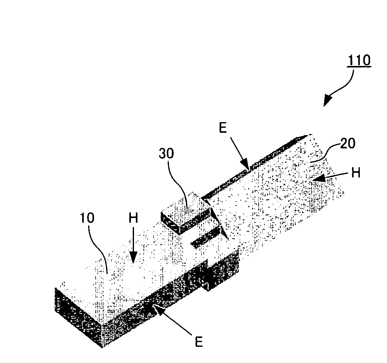
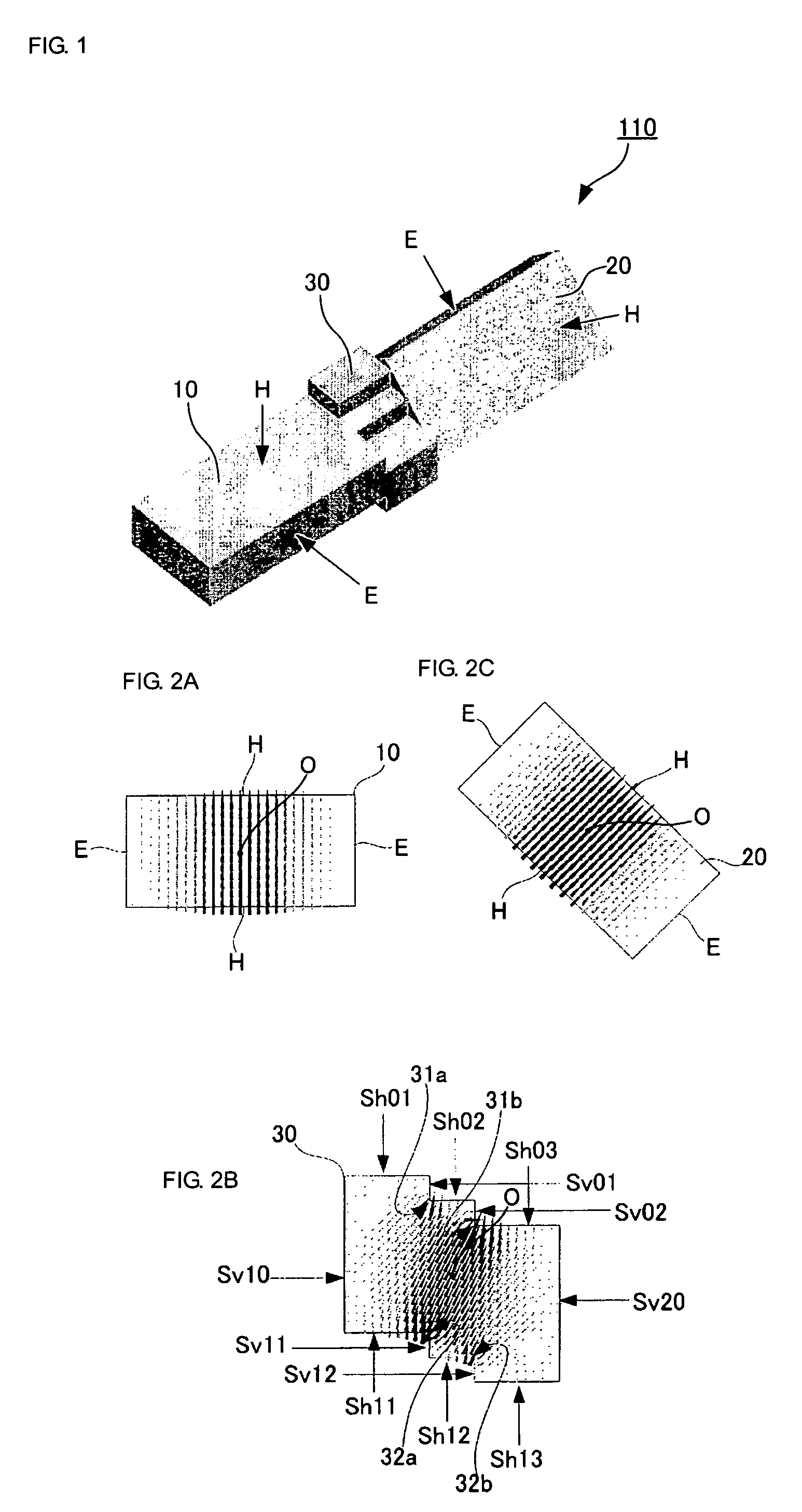
[0044]A twisted waveguide will now be described with reference to FIGS. 1 to 3.
[0045]FIG. 1 is a perspective view illustrating a three-dimensional configuration of an inside (electromagnetic-wave propagation path) of a twisted waveguide 110. The twisted waveguide 110 includes a first rectangular waveguide element 10 corresponding to a first rectangular propagation path; a second rectangular waveguide element 20 corresponding to a second rectangular propagation path element; and a connection element 30 connecting the first rectangular waveguide element 10 and the second retangular waveguide element 20. The first rectangular waveguide element 10 and the second rectangular waveguide element 20 propagate an electromagnetic wave of TE10 mode and each have an H plane extending longitudinally and an E plane extending laterally when viewed in cross section taken along a plane perpendicular to a direction of electromagnetic-wave propagation. The reference characters H in FIG. 1 each indicat...
fourth embodiment
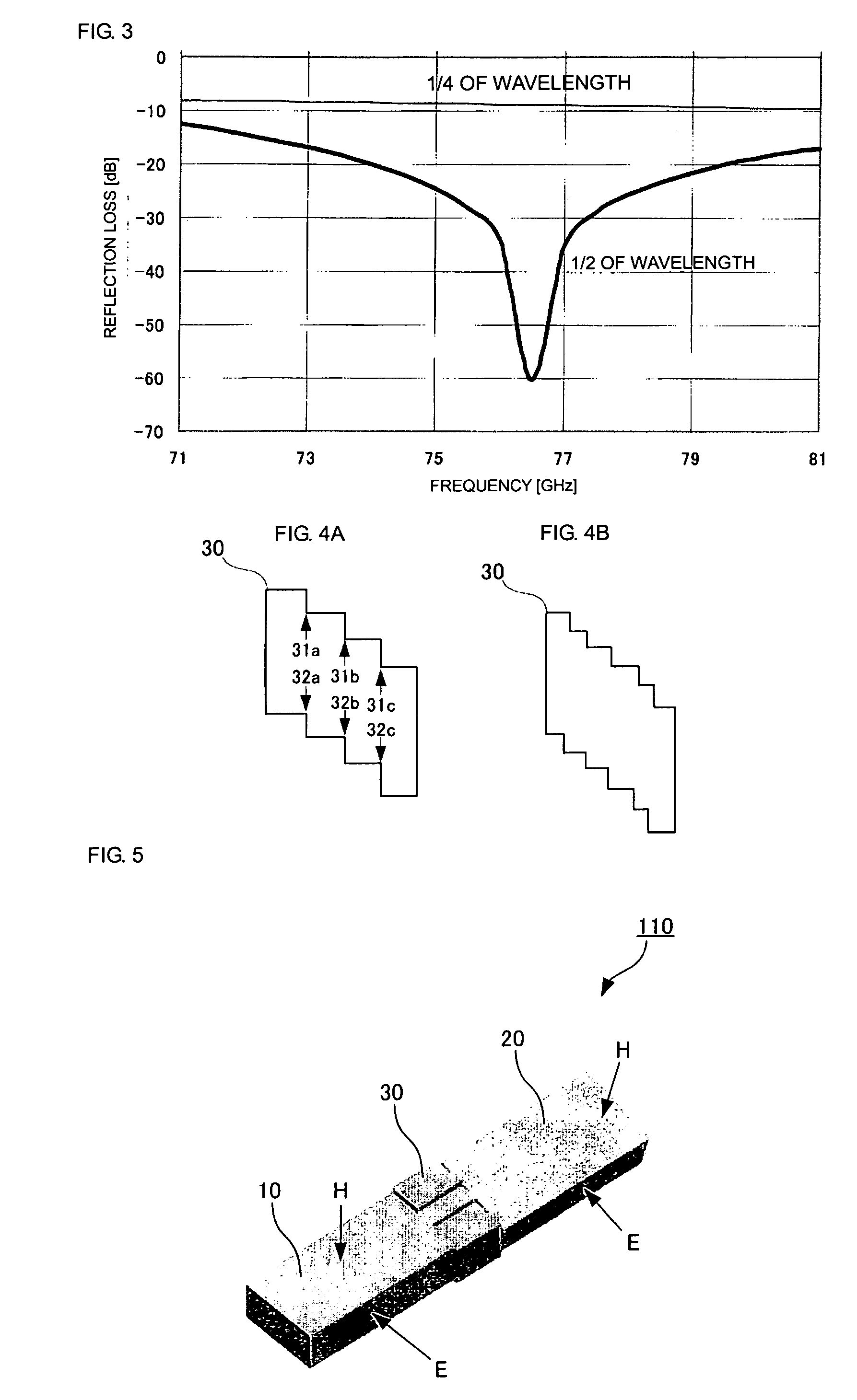
[0055]FIG. 5 illustrates a twisted waveguide according to a In this embodiment, H plane of the second rectangular waveguide element 20 is inclined at an angle of 15° with respect to H plane of the first rectangular waveguide element 10. This means that the connection element 30 rotates the plane of polarization of an electromagnetic wave propagating through the connection element 30 by an angle of 15°. Consequently, when the rotation angle is to be reduced, the angle of inclination of the staircase portion of the connection element 30 is made smaller, whereby the height of each step of the staircase is reduced. In contrast, if the rotation angle is to be increased, the angle of inclination of the staircase portion of the connection element 30 is made larger, whereby the height of each step of the staircase is increased.
fifth embodiment
[0056]A twisted waveguide will now be described with reference to FIGS. 6A through 7D.
[0057]Each of the drawings mentioned above illustrates only the internal structure of the electromagnetic-wave propagation path. Specifically, the twisted waveguide can be be formed by assembling together a plurality of metal blocks having grooves formed therein by, for example, cutting. FIGS. 6A–6C show three examples of such an assembly. Each diagram is a cross-sectional view of the connection element taken along a plane perpendicular to the direction of electromagnetic-wave propagation. A broken line in the diagrams corresponds to an attachment plane (dividing plane) between metal blocks. The relationship between the connection element and the first and second rectangular waveguide elements is the same as that shown in FIGS. 1 and 2. In each of FIGS. 6A and 6C, a plane parallel to H plane of the first rectangular waveguide element functions as a dividing plane. Specifically, in FIG. 6A, the div...
PUM
 Abstract
Description
Claims
Application Information
 - R&D
- Intellectual Property
- Life Sciences
- Materials
- Tech Scout
- Unparalleled Data Quality
- Higher Quality Content
- 60% Fewer Hallucinations
Browse by: Latest US Patents, China's latest patents, Technical Efficacy Thesaurus, Application Domain, Technology Topic, Popular Technical Reports.
© 2025 PatSnap. All rights reserved.Legal|Privacy policy|Modern Slavery Act Transparency Statement|Sitemap|About US| Contact US: help@patsnap.com


