
Coaxial plug-and-socket connector having resilient tolerance compensation

a resilient tolerance and connector technology, applied in the direction of coupling contact members, fixed connections, coupling device connections, etc., can solve the problems of repeatability of mating, unwanted change in contact zone, and definite adverse effect on the quality of electrical transmission, so as to eliminate unwanted change in field resistance

Active Publication Date: 2007-05-01
ROSENBERGER HOCHFREQUENZTECHNIK GMBH & CO KG
View PDF24 Cites 22 Cited by
  • Summary
  • Abstract
  • Description
  • Claims
  • Application Information

AI Technical Summary

Benefits of technology

The design enhances repeatability and maintains a stable contact zone, ensuring reliable electrical connections despite relative movements, while simplifying manufacturing and reducing costs.

Problems solved by technology

Although coaxial plug-and-socket connectors of this kind normally meet the requirements they are called upon to meet sufficiently well, it has nevertheless been found that certain serious disadvantages do occur, doing so particularly at the high transmission frequencies which can be expected today, which may be as much as 60 GHz or more.
These disadvantages arise because even slight relative movements between the printed circuit boards which are connected together, both in the axial direction of the contact pins and also transversely thereto, cause an unwanted change in the contact zone between the contact pin of the center conductor and the center-conductor member of the female coupler.
This in turn results in an unwanted change in the field resistance preset by the defined air-gap, which has a definite adverse effect on the quality of the electrical transmission.
These relative movements between the printed circuit boards, slight though they are, cannot be avoided and because of them there is no assurance, even with the known plug-and-socket connectors, that what is called repeatability of mating will remain the same, which is likewise considered a disadvantage.

Method used


Image

  • Coaxial plug-and-socket connector having resilient tolerance compensation
  • Coaxial plug-and-socket connector having resilient tolerance compensation

Examples


Embodiment Construction

)

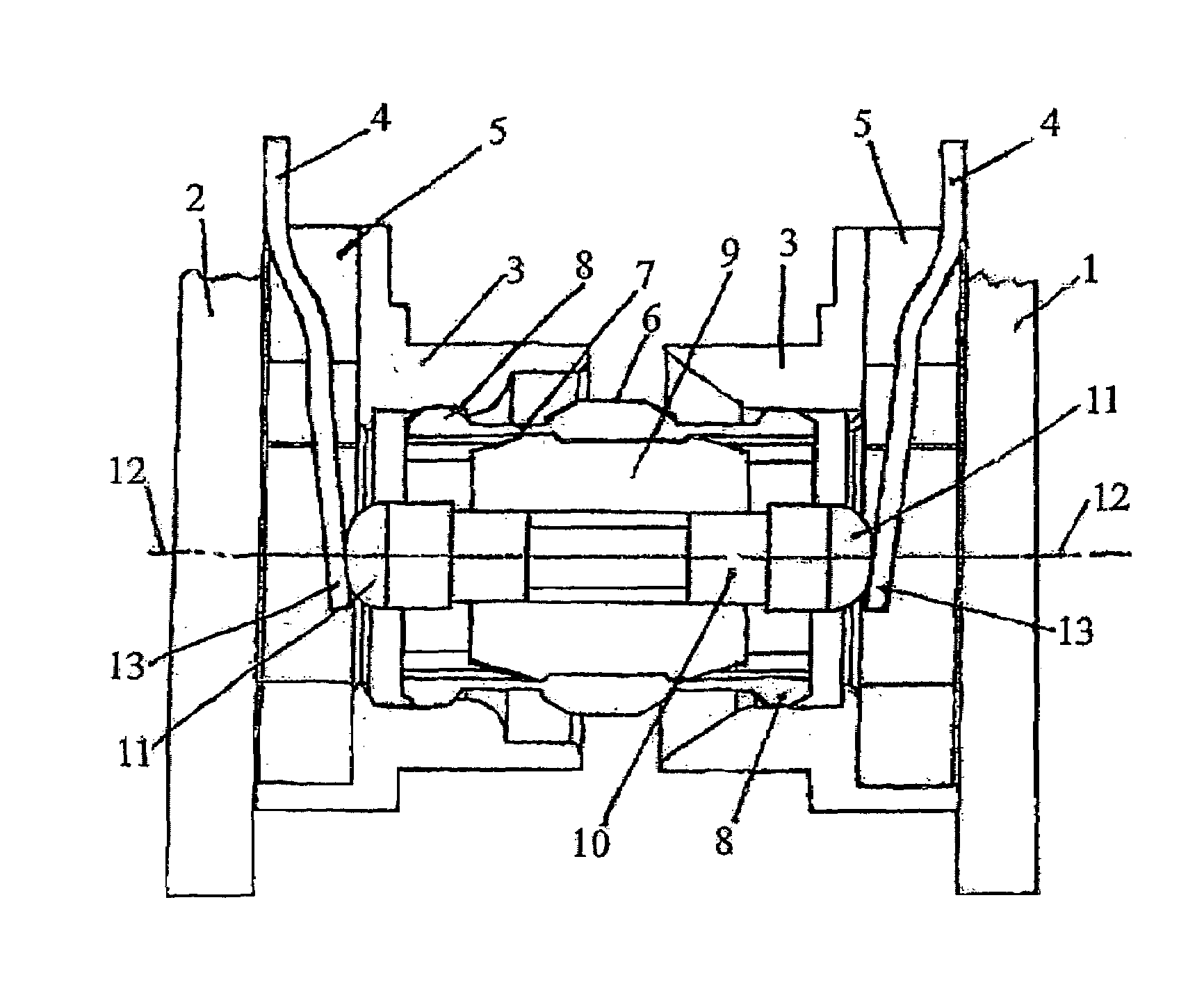
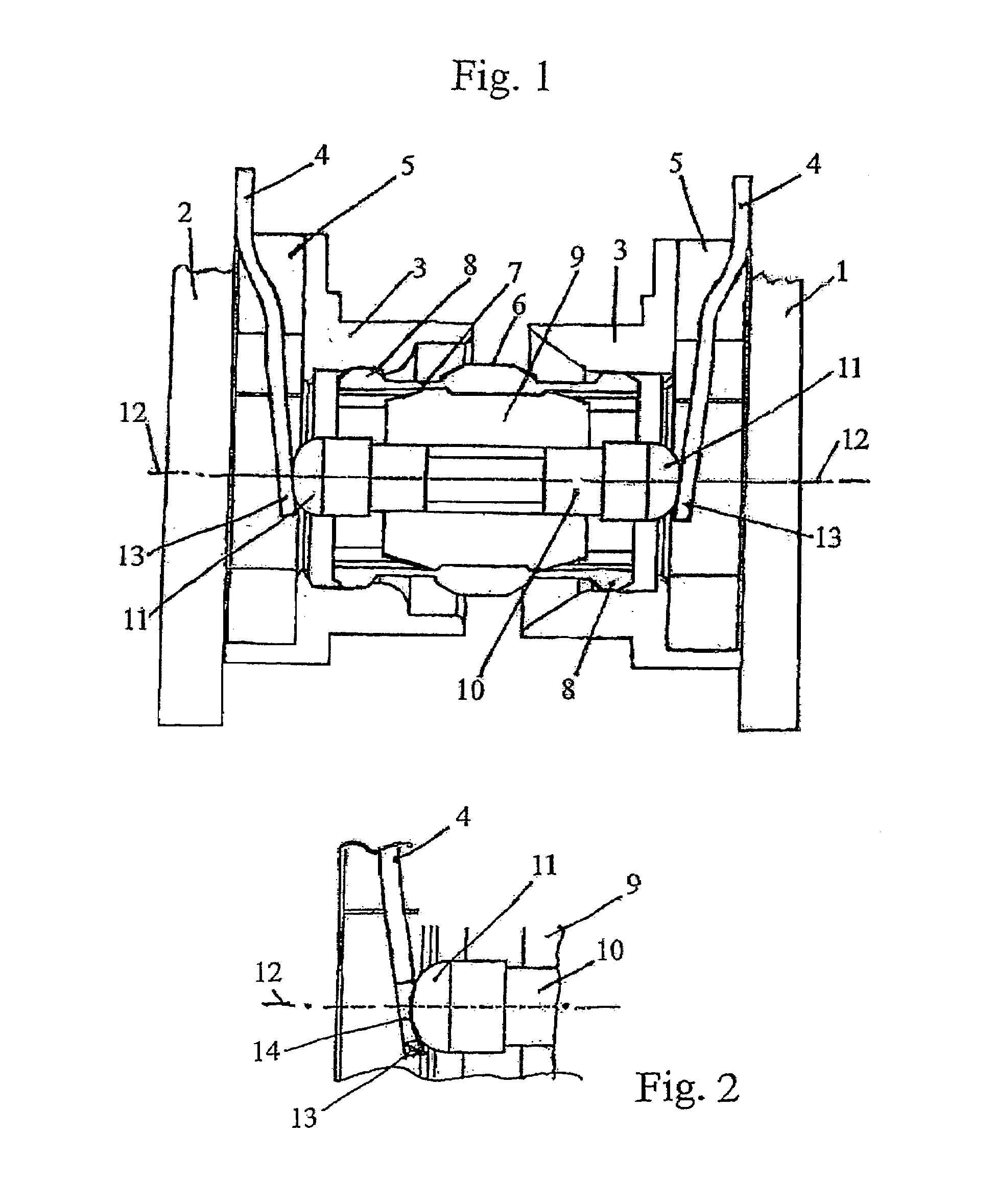
[0021]In the case of the coaxial plug-and-socket connector according to the invention, the design is such that the center conductor of the printed circuit board is in the form of a resilient member of planar form which is held in place at the printed circuit board or at an insulator at one of its ends and at its other, free end can be brought into engagement with the center-conductor member of the plug-in coupler, which center-conductor member is in the form of a contact pin.

[0022]In an advantageous embodiment of the invention, the resilient member of planar form is of a tongue-like or strip-like form, which ensures that manufacture will be easy.

[0023]It is ensured that the contact between the center conductor of the printed circuit board and the center-conductor member, in the form of a contact pin, of the plug-in coupler is always good when, as is provided for in accordance with the invention, the resilient member of planar form is held in place under preloading.

[0024]The free en...


PUM


Abstract

A coaxial plug-in connection, particularly for printed circuit boards. An outer and inner conductor are assigned to each board, and can be electrically connected to the outer or inner conductor of the other respective board via a sleeve-shaped plug-in adapter coupling that encompasses a corresponding outer conductor portion and an inner conductor portion. The inner conductor of the printed circuit board is a spring metal sheet, one end of which is fixed to the board or an insulating element, while the other end is free to engage with the inner conductor portion of the plug-in coupling, which is configured as a contact pin.

Description

BACKGROUND OF THE INVENTION[0001]1. Field of the Invention[0002]The invention relates to a coaxial plug-and-socket connection, specifically for printed circuit boards.[0003]2. Description of Related Art[0004]In known coaxial plug-and-socket connectors of this kind, such as that described in German Patent No. DE 202 08 425.6, at least one socket forming an outer conductor and having an associated center conductor is usually fixed to each printed circuit board. The center conductor has, in this case, a contact pin, normally cylindrical, which can be plugged, in such a way as to be held in place resiliently, into a correspondingly shaped recess in the end-face of the center-conductor member of an adapter in the form of a sleeve-like plug-in coupler. The design is such that a defined air-gap is left between the outer-conductor socket and the end-face of the plug-in coupler.[0005]Although coaxial plug-and-socket connectors of this kind normally meet the requirements they are called upon ...

Claims


Application Information

Patent Timeline
Patent Type & Authority Patents(United States)
IPC IPC(8): H01R12/00H01R13/24H01R13/631H01R13/646H01R31/06
CPCH01R13/2464H01R23/6873H01R24/50H01R24/54H01R12/52H01R13/6315H01R31/06H01R2103/00H01R24/542H01R13/658H01R12/73
Inventor ROSENBERGER, BERND
Owner ROSENBERGER HOCHFREQUENZTECHNIK GMBH & CO KG
Learn More