
Image cropping and synthesizing method, and imaging apparatus

a technology applied in the field of image cropping and synthesizing method, imaging apparatus, can solve the problem of time-consuming operation, and achieve the effect of facilitating cropping and synthesizing an imag

Inactive Publication Date: 2007-04-24
FUJIFILM HLDG CORP +1
View PDF14 Cites 144 Cited by
  • Summary
  • Abstract
  • Description
  • Claims
  • Application Information

AI Technical Summary

Benefits of technology

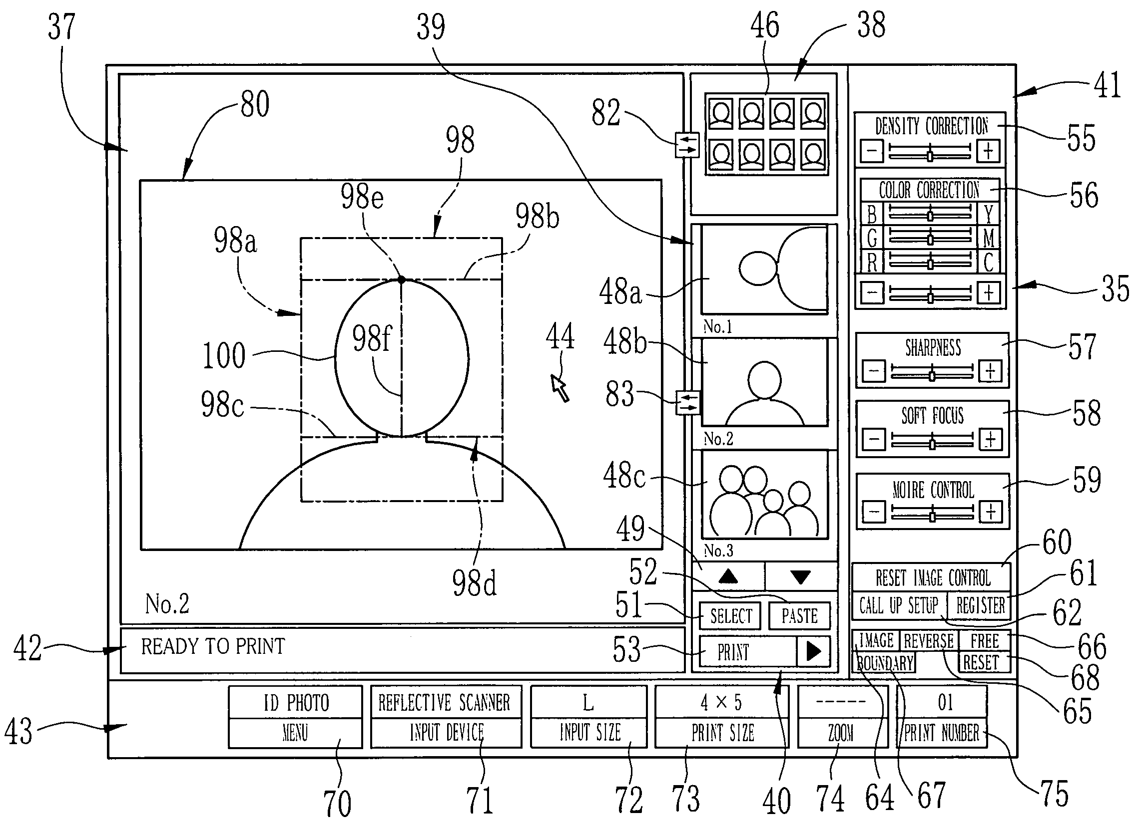
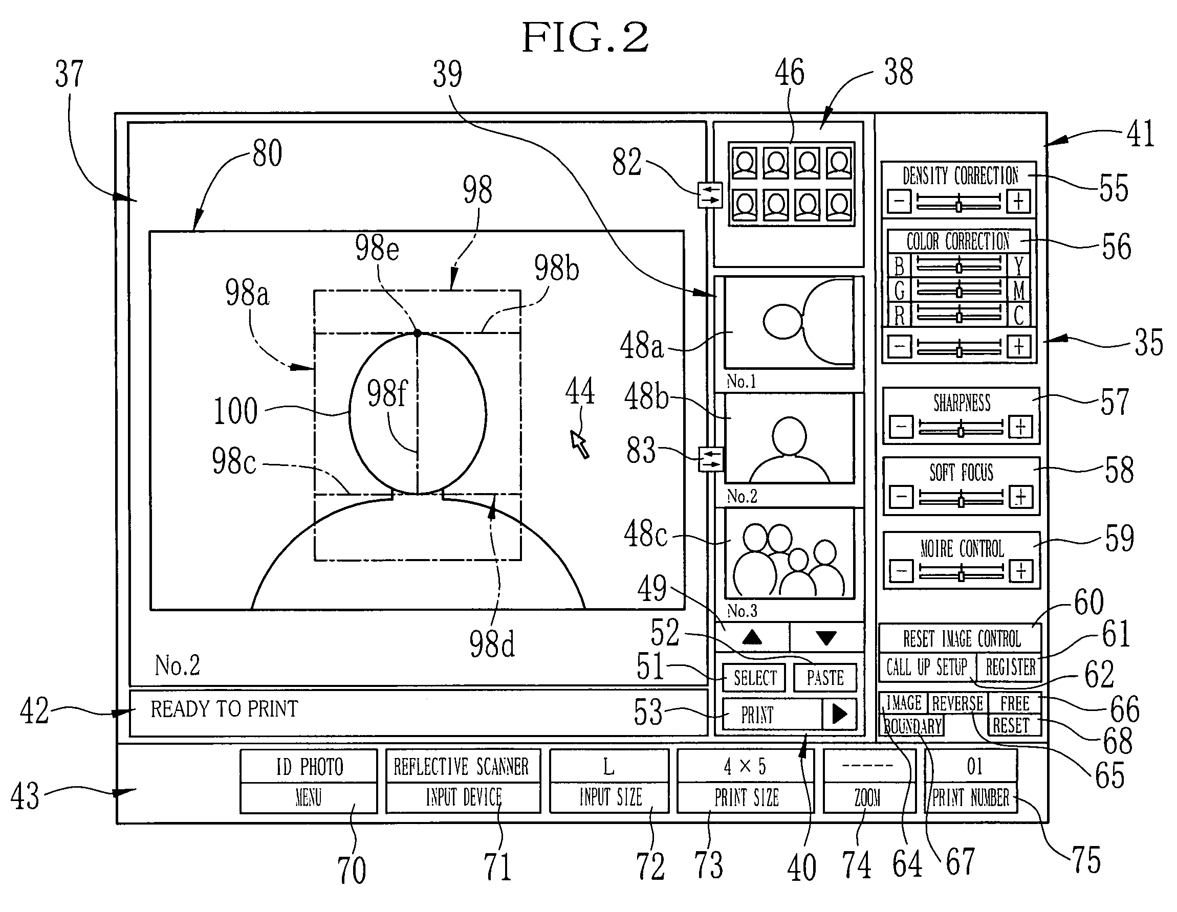
The present invention provides an image cropping and synthesizing method and apparatus that make it easy to cropping and synthesizing an image with a template in a proper format. The method involves displaying a crop boundary with a reference point on an image, selecting a template with at least a frame, moving the crop boundary on the screen to position the reference point, enlarging or reducing the crop boundary about the reference point, cropping the image of the bounded area, and pasting the cropped image in the frame of the template. The apparatus includes a template selecting device, a display device, an operation device, a cropping device, and an image synthesizing device. The technical effects of the invention include simplifying the process of cropping and synthesizing an image with a template, making it easier to layout a portion of the image in a designated size and position relative to the outline of the frame, and improving the overall quality of the synthesized image.

Problems solved by technology

Accordingly, it requires some skill or several trial and error to synthesize the image with the template properly, and thus this operation has been time consuming.

Method used


Image

  • Image cropping and synthesizing method, and imaging apparatus
  • Image cropping and synthesizing method, and imaging apparatus
  • Image cropping and synthesizing method, and imaging apparatus

Examples


Embodiment Construction

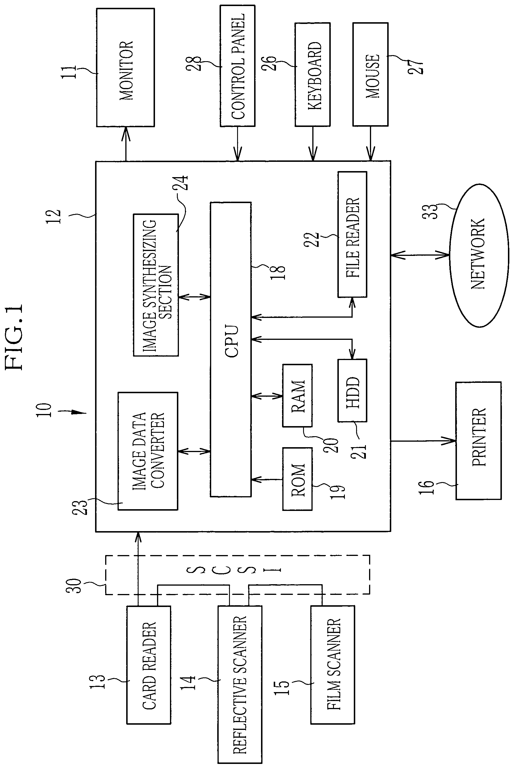
[0031]In FIG. 1, an imaging system 10 is mainly constituted of a personal computer 12, a monitor 11 as a display device, and a card reader 13, a reflective scanner 14 and a film scanner 15 as image input devices, and a printer 16. The monitor 11, the image input devices 13 to 15 and the printer 16 are connected to the personal computer 12. The printer 16 prints out hard copies of images processed in the personal computer 12. In this embodiment, the printer 16 is of a type that uses a heat-developing photosensitive recording material.

[0032]The personal computer 12 consists of a CPU 18, a ROM 19, a RAM 20, a hard disc drive (HDD) 21, a file reader 22, an image data converter 23 and an image synthesizing section 24. For example, the file reader 22 is a floppy disc drive, and may read out image data from a floppy disc. In that case, the file reader 22 is used as an image input device.

[0033]A keyboard 26, a mouse 27 and a control panel 28 are also connected to the personal computer 12. T...


PUM


Abstract

By selecting a template, a crop boundary (98a) is displayed on an image on a screen. The crop boundary has a corresponding shape to that of a frame of the selected template, and is variable in size while keeping the same shape and being centered on a reference point (98e). Upper and lower horizontal lines (98b, 98c) are also displayed inside the crop boundary to define an internal zone (98d), and the center point on the upper horizontal line is defined as the reference point. By placing the reference point on the top of the head of a human subject contained in the displayed image and then moving the lower horizontal line to align it with the chin, the internal zone is adjusted to the head of the human subject. In cooperation with the movement of the lower reference line, the crop boundary is automatically enlarged or reduced so as to keep the internal zone in a predetermined proportion and position relative to the crop boundary.

Description

BACKGROUND OF THE INVENTION[0001]1. Field of the Invention[0002]The present invention relates to an image cropping and synthesizing method, and more particularly to a method of cropping an image and synthesizing the cropped image with a template. The present invention relates also to an imaging apparatus for the image cropping and synthesizing method.[0003]2. Background Arts[0004]An imaging system has been known in the art, wherein electronic images are taken out from different kinds of storage media, and are processed for correcting the image quality or for synthesizing with an optional template image, to print out hard copies of the electronic images. The imaging system consists of image input devices, a computer and a printer. As the image input devices, there are a reflective scanner that reads out electronic images from reflective originals, such as a photo-print printed on photographic paper and other kinds of printed matters printed on reflective recording material, a film sc...

Claims


Application Information

Patent Timeline
Patent Type & Authority Patents(United States)
IPC IPC(8): G09G5/00G06T11/60G06F3/033G06F3/048G06T3/00H04N1/387H04N1/393H04N5/222H04N5/262
CPCG06F3/0481G06T11/60
Inventor JOGO, NAOZUMI
Owner FUJIFILM HLDG CORP
Learn More