Torque fluctuation absorbing device
a technology of torque fluctuation and absorbing device, which is applied in the direction of couplings, slip couplings, gearing, etc., can solve the problems of excessive torque input to the transmission and deterioration of vehicle accelerating performan
- Summary
- Abstract
- Description
- Claims
- Application Information
AI Technical Summary
Benefits of technology
Problems solved by technology
Method used
Image
Examples
first embodiment
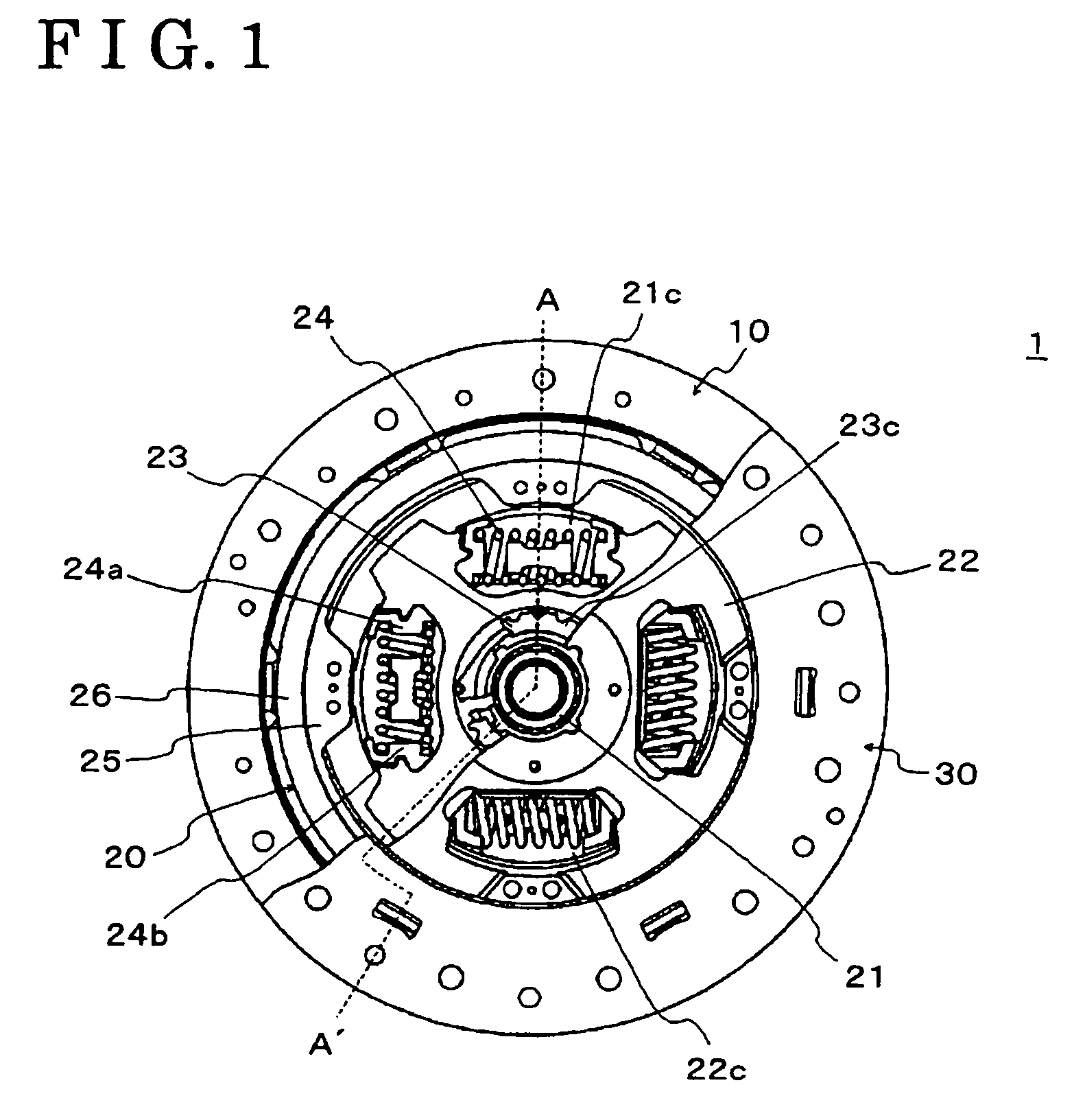
[0030]The damping mechanism 20 includes a hub 21, a side plate 22, a thrust member 23, a damper 24, a disc 25, a pair of frictional members 26 and a rivet. The hub 21 is integrally provided with a flange portion 21a extending radially outwardly. The hub 21 is further provided with a spline portion 21b at an inner surface of a central bore thereof, which is spline engaged with the transmission input shaft. There are at least one notched portion 21c defined at a radially outer side of the flange portion 21a. According to the present invention, there are four notched portions 21c defined at a radially outer side of the flange portion 21a. A pair of spring seats 24a is disposed in each notched portion 21c, and an outer peripheral surface of the spring seat 24a is positioned to be outside of a radially outer side of an outer peripheral surface of the flange portion 21a.
[0031]The side plate 22 includes a first side plate 22A and a second side plate 22B. As illustrated in FIG. 2, the firs...
second embodiment
[0047]Next, the following explanation will be given for explaining the present invention with reference to FIGS. 4A, 4B, 5A and 5B.
[0048]In the torque fluctuation absorbing device 1 according to the second embodiment of the present invention, there is a difference in a structure of the frictional members 26 fixed at the disc 25 from the one according to the first embodiment of the present invention. The other components of the torque fluctuation absorbing device 1 according to the second embodiment of the present invention possess the same construction as the ones according to the first embodiment and so a detailed description thereof will be omitted hereinbelow.
[0049]In order to improve the contact performance of each frictional member 26, at least one of the frictional members 26 has a non-frictional portion (i.e., groove 26a) ranging substantially between 20 percents and 80 percents of an entire frictional surface area of the at least one of the frictional members 26. It is prefe...
third embodiment
[0054]Next, the following explanation will be given for explaining the present invention with reference to FIGS. 6A and 6B.
[0055]In the torque fluctuation absorbing device 1 according to the third embodiment of the present invention, there is a difference in a structure of the frictional member 26 fixed at the disc 25 from the one according to the first embodiment of the present invention. The other components of the torque fluctuation absorbing device 1 according to the third embodiment of the present invention possess the same construction as the ones according to the first embodiment of and so a detailed description thereof will be omitted hereinbelow.
[0056]In order to improve the contact performance of each frictional member 26, at least one of the frictional members 26 is configured with plural block-shaped frictional materials. The frictional member 26 is allocated at the disc 25 so as to set a frictional surface of the frictional member 26 substantially between 20 percents an...
PUM
 Abstract
Description
Claims
Application Information
 - R&D
- Intellectual Property
- Life Sciences
- Materials
- Tech Scout
- Unparalleled Data Quality
- Higher Quality Content
- 60% Fewer Hallucinations
Browse by: Latest US Patents, China's latest patents, Technical Efficacy Thesaurus, Application Domain, Technology Topic, Popular Technical Reports.
© 2025 PatSnap. All rights reserved.Legal|Privacy policy|Modern Slavery Act Transparency Statement|Sitemap|About US| Contact US: help@patsnap.com


