Electrical connector with a detective switch

a technology of electrical connectors and switches, applied in the direction of coupling devices, two-part coupling devices, electrical apparatus, etc., can solve the problems of repeated use of switches, and achieve the effect of good detective functions

Inactive Publication Date: 2007-04-24
HON HAI PRECISION IND CO LTD
View PDF9 Cites 78 Cited by
  • Summary
  • Abstract
  • Description
  • Claims
  • Application Information

AI Technical Summary

Benefits of technology

[0007]Accordingly, an object of the present invention is to provide an electrical connector having a good detective function.

Problems solved by technology

Under this condition, the projecting portion 3211′ is therefore very short with little elasticity, and thus the switch function due to repeated usage may fail.

Method used


Image

  • Electrical connector with a detective switch
  • Electrical connector with a detective switch
  • Electrical connector with a detective switch

Examples


Embodiment Construction

[0018]Reference will now be made in detail to the preferred embodiment of the present invention.

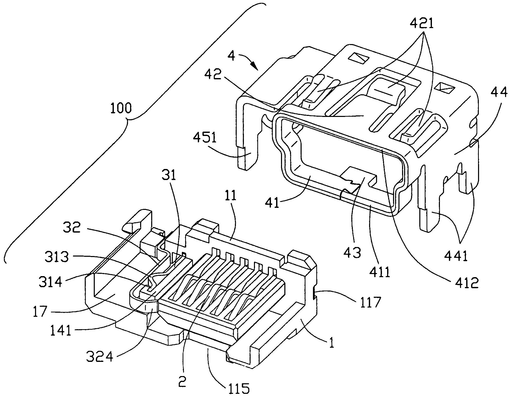
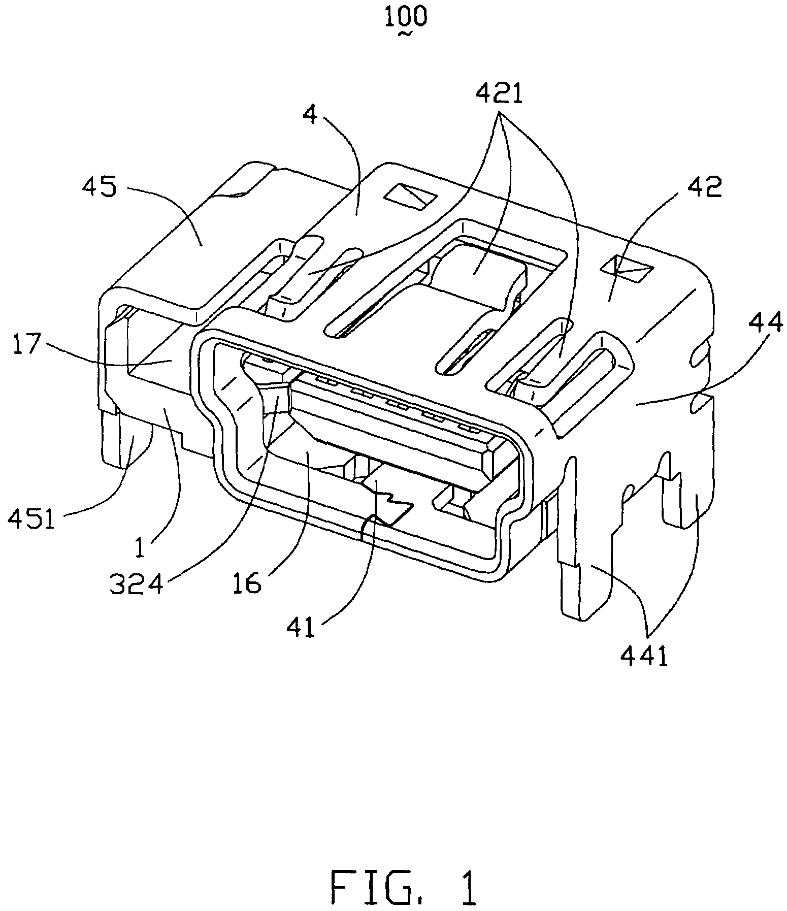
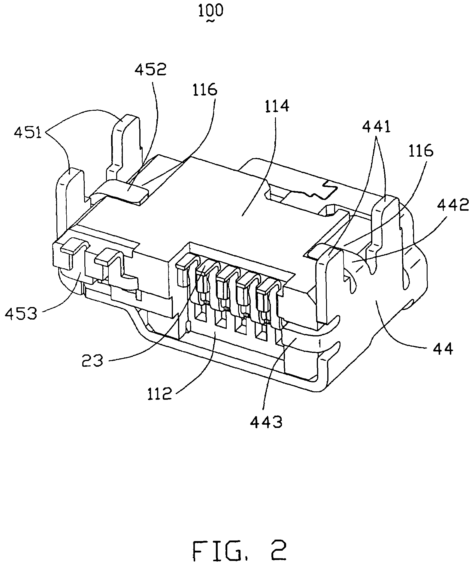
[0019]Referring to FIGS. 1–3, an electrical connector 100 mounted on a printed circuit board (PCB, not shown) for electrically connecting with a complementary mating connector (not shown), comprises an insulative housing 1, a plurality of conductive contacts 2, and a detective switch 3 retained in the housing 1, as well as an outer shield 4 enclosing the insulative housing 1. The electrical connector 100 of the preferred embodiment is a mini USB connector. The detective switch 3 further includes a stationary switch 31 and a movable switch 32 for engaging / disengaging with the stationary switch 31 according to whether or not the mating connector is inserted into the electrical connector 100.

[0020]The insulative housing 1 includes a slight base portion 11, a cavity 16 for receiving the mating connector, a tongue plate 12 extending forward from the front wall 111 of the base portion 11 into t...


PUM


Abstract

An electrical connector (100) for electrically connecting with a mating connector, includes an insulative housing (1) defining a cavity (16), a number of contacts (2) extending into the cavity, and a detective switch (3) accommodated in the housing (1). The detective switch includes a stationary switch (31) and a movable switch (32). The stationary switch and the movable switch respectively include a first and a second engaging portion (313, 323) for connecting / disconnecting with each other. The movable switch (32) includes a spoon-shaped projecting portion (324) positioned in a free end of the second engaging portion (323) and extending into the cavity (16) for engaging with the mating connector.

Description

BACKGROUND OF THE INVENTION[0001]1. Field of the Invention[0002]This invention generally relates to an electrical connector, and more particularly to an electrical connector with a detective switch.[0003]2. Description of the Prior Art[0004]Referring to FIGS. 6–7, U.S. publication No. 20050227524 A1 discloses a modular jack which includes an insulative housing 1′ defining a cavity 151′ therein, a contact module with a plurality of conductive contacts, and a detective switch 3′ disposed in the housing 1′. The detective switch 3′ includes a stationary switch 31′ and a movable switch 32′ for mating with the stationary switch 31′. The stationary switch 31′ and the movable switch 32′ respectively include an engaging portion 311′, 3212′ for electrically connecting with each other. The movable switch 32′ further has a projecting portion 3211′ interiorly bending from the middle section thereof. The projecting portion 3211′ extends into the cavity 151′ for engaging with a complementary plug....

Claims


Application Information

Patent Timeline
Patent Type & Authority Patents(United States)
IPC IPC(8): H01R29/00
CPCH01R13/703H01R24/62
Inventor CHEN, MING-CHING
Owner HON HAI PRECISION IND CO LTD
Why Eureka
Try Eureka