
Broad-band fiber-optic wave plates

a fiber-optic wave plate and wide-band technology, applied in the field of polarization-transforming fibers and specialized fibers, can solve the problems of large bulky overall composite layout, vibration-sensitive, scarcely practical to use a short hi-bi fiber section of very precise length to serve the purpose of a desired sop transformation

Inactive Publication Date: 2007-04-17
HUANG HUNG CHIA
View PDF6 Cites 7 Cited by
  • Summary
  • Abstract
  • Description
  • Claims
  • Application Information

AI Technical Summary

Problems solved by technology

In modern fiber-optic systems, while such bulk-optic wave plates can be incorporated with the optical fiber circuitry to perform a prescribed state-of-polarization (SOP) transform function, the overall composite layout is likely bulky and vibration-sensitive, requiring careful and deliberate manual tuning and adjustments in maintenance of the system operation.
More remarkably, a bulk-optic wave plate structured by a calcite crystal of precise thickness is inherently narrow-band, and this is oftentimes a restrictive feature for its inclusion in modern optical fiber communication and sensor technology.
In actual practice, however, it scarcely appears practical to use a short hi-bi fiber section of very precise length to serve the purpose of a desired SOP transformation, particularly in view of an all-fiber optical circuitry wherein each fiber element is preferably in-line spliced at either end of the element.

Method used


Image

  • Broad-band fiber-optic wave plates
  • Broad-band fiber-optic wave plates
  • Broad-band fiber-optic wave plates

Examples


first embodiment

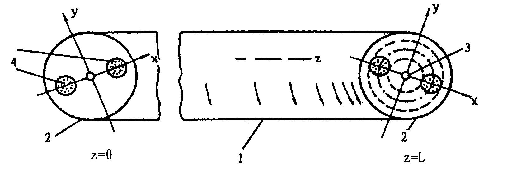
[0036]According to the invention, a broad-band fiber-optic wave plate is provided which is characterized by the specification of a broad-band fiber-optic quarter wave plate, called a PPT (short for practical polarization transformer) or simply PT. As afore-said, a fiber-optic wave plate is a section of variably spun birefringent optical fiber. The structural feature of a quarter wave plate is that the spin-rate varies slowly along the fiber section from zero to fast, or conversely from fast to zero. A PPT is thus an asymmetrical fiber structure comprising four different versions in view of the circumstance that either the unspun end or the fast-spun end can act as the input, and in each case, the sense of spin can be either clockwise or anticlockwise.

[0037]With reference to FIG. 1, a schematic diagram of the structure of a broad-band fiber-optic quarter wave plate is shown in the form of a variably spun birefringent optical fiber with a spin-rate varying from zero to fast, wherein t...

second embodiment

[0051]According to the invention, a broad-band fiber-optic wave plate is provided which is characterized by the specification of a broad-band fiber-optic half wave plate. With reference to FIG. 3, such fiber-optic wave plate is a section of spun birefringent optical fiber with one end being fast-spun and the other end being fast-spun but in opposite sense, and with a spin-rate varying slowly from fast to zero, and thence in opposite sense of spinning from zero to fast. The two subsections of fiber, fast-to-zero and zero-to-fast, are not required to be exactly antisymmetrical in their spin-rate functions. What is required is that both fast-spun ends are spun at sufficiently fast rates, and the variation of the spin-rate is always slow enough. Two behaviors of a fiber-optic half wave plate are of interest. One behavior is that a linear light incident onto one end of this wave plate is transformed into a linear light at the other end with a phase shift of π. Another behavior is that, w...

third embodiment

[0052]According to the invention, a broad-band fiber-optic wave plate is provided which is characterized by the specification of a broad-band fiber-optic full wave plate. With reference to FIG. 4A, one variety of fiber-optic full wave plate is a section of spun birefringent optical fiber with one end being fast-spun and the other end being fast-spun in the same sense, wherein the spin-rate variation from fast to zero in the first subsection and in the same sense from zero to fast in the second subsection is always sufficiently slow over the entire length of the fiber. With reference to FIG. 4B, another variety of fiber-optic full wave plate is a section of birefringent optical fiber whose spin-rate varies from zero to fast in the first subsection and thence continuously from the attained fast value to zero. The SOP transforms of interest with respect to said two varieties of fiber-optic full wave plate are listed in Table 4.

[0053]

TABLE 4Polarization Transforms of Fiber-Optic Full Wa...


PUM


Abstract

A section of birefringent optical fiber spun at a slowly varying spin-rate from zero to a high value, or vice versa, behaves as a fiber-optic quarter wave plate in polarization transforms. Despite this similarity in SOP transforms with its bulk-optic counterpart which is narrow-band, this invention works on an entirely different mechanism that favorably makes the invention broad-band. Using different spin-rate functions, the invention is extended to include broad-band fiber-optic half wave, full wave, and fractional wave plates, capable of performing polarization transforms like the respective bulk-optic counterparts. Fabrication of the invented broad-band fiber-optic wave plates can be performed in the conventional way by using a birefringent preform drawn by a fiber-drawing tower incorporated with a variable-speed spinner on top of the setup. A nonconventional way is to use the moving microheater technique, devised by the same inventor, using a length of birefringent fiber as the starting material. The invention finds immediate and potential applications in all-fiber optical circuitry, an electric current sensing architecture for example, wherein circular light is used along with linear light.

Description

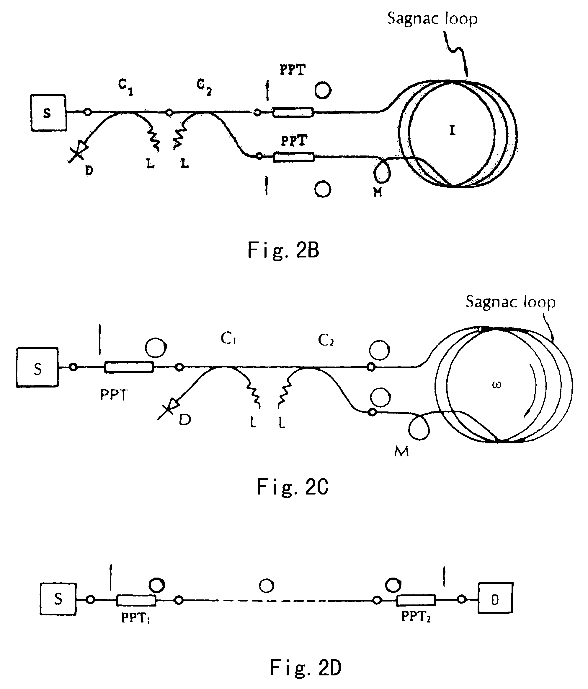
BACKGROUND OF THE INVENTION[0001]1. Field of the Invention[0002]This invention relates to polarization-transforming fiber, specialized fiber, polarization optics in specialized fiber, optical fiber circuitry and networks involving use of circular light, all-fiber optical architecture for gyroscope, electric-current sensor, and coherence optical fiber communication, fiber-optic interferometers, Sagnac interferometer, etc. In particular, this invention relates to broad-band fiber-optic wave plates.[0003]2. Description of the Related Art[0004]In any optics laboratory, conventional bulk-optic wave plates are versatile elements widely used in lightwave experiment. Thus, a bulk-optic quarter wave plate is commonly used to convert a linear light into a circular light, or conversely a circular light into a linear light. A bulk-optic half wave plate is commonly used to change the orientation of a linear light. In modern fiber-optic systems, while such bulk-optic wave plates can be incorporat...

Claims


Application Information

Patent Timeline
Patent Type & Authority Patents(United States)
IPC IPC(8): G02B6/00
CPCG01C19/721G02B6/024G02B6/105G02B6/274
Inventor HUANG, HUNG-CHIA
Owner HUANG HUNG CHIA
Learn More