Pen input display device

Active Publication Date: 2007-04-17
SHARP KK
View PDF3 Cites 3 Cited by
  • Summary
  • Abstract
  • Description
  • Claims
  • Application Information

AI Technical Summary

Benefits of technology

[0042]The present invention was made in view of the foregoing problems, and accordingly it is an object of the present invention to provide a pen input display device of an ultrasonic pen input system for preventing errors over the entire input area of the display panel, without increasing power consumption or impairing operability of pen entry.
[0045]However, according to the foregoing configuration, the distance detecting section directly or indirectly detects a distance between the ultrasonic transmitter and each of the ultrasonic receivers, and the received waveform control section carries out the control of reducing a difference in level of the respective received waveforms in the ultrasonic receiving section based on the result of detection. In this way, the errors caused by different levels of the received waveforms can be restricted. As a result, a pen input display device is provided that can prevent errors over the entire input area of the display panel.

Problems solved by technology

Errors occur when the received waveforms are at different levels.

Method used


Image

  • Pen input display device
  • Pen input display device
  • Pen input display device

Examples


first embodiment

[0069][First Embodiment]

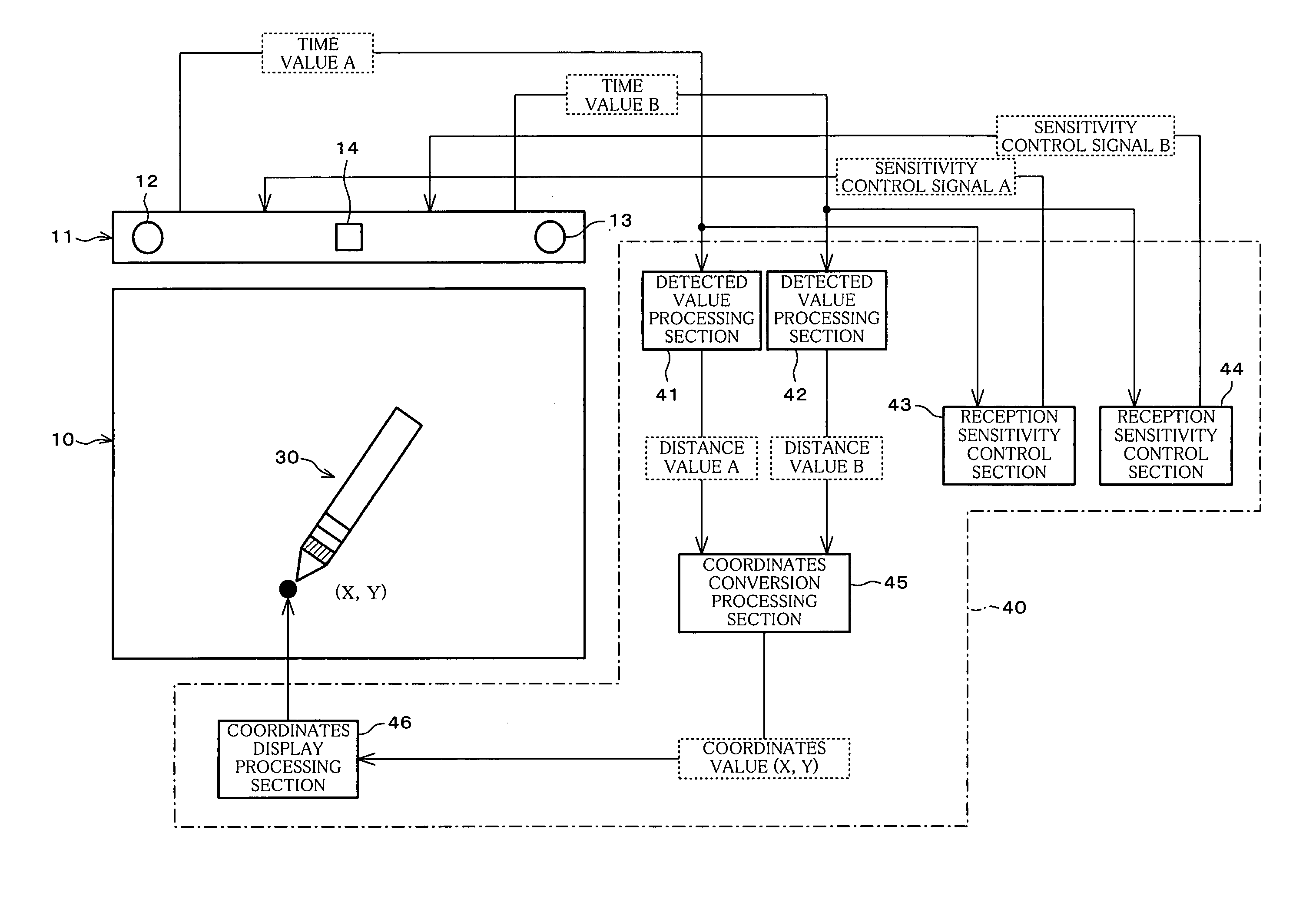
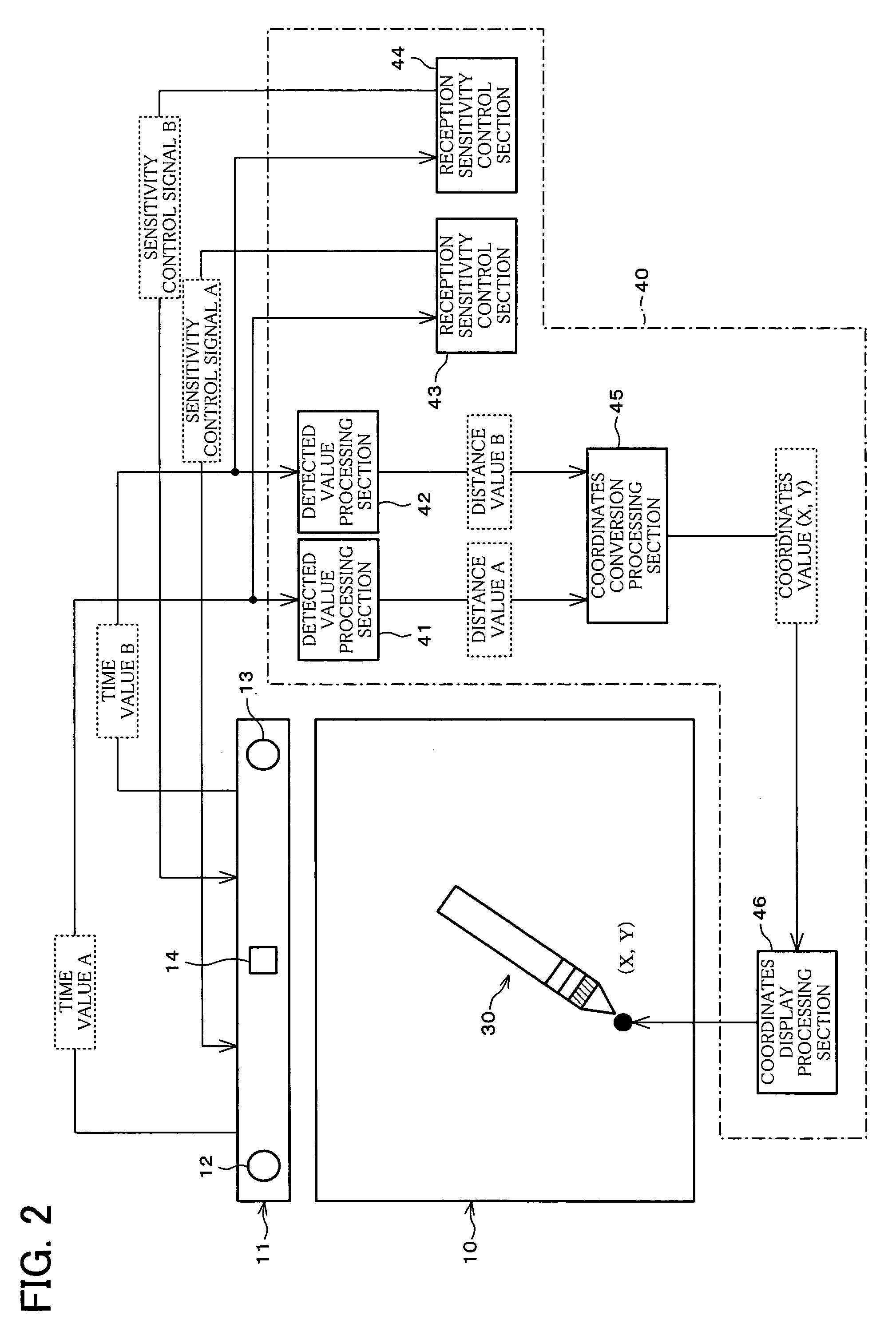
[0070]One embodiment of the present invention is described below with reference to the attached drawings. First, reference is made to FIG. 2 to describe a configuration of a pen input display device according to this embodiment.

[0071]The pen input display device according to the present embodiment is one form of a display device of an input / output-integrated type, in which pen entry is directly made to a display panel. The pen input display device includes a display panel 10, a pen input unit 11, an input pen 30, and a display control unit 40, as illustrated in FIG. 2. In the configuration shown in FIG. 2, the display panel 10 and the input pen 30 are similar to the display panel 100 and the input pen 120, respectively, described earlier with reference to FIG. 16.

[0072]Specifically, in the pen input display device according to the present embodiment, the pen input unit 11 is disposed in the vicinity of the display panel 10, and two ultrasonic receivers 12 and...

second embodiment

[0087][Second Embodiment]

[0088]In the pen input display device according to the foregoing First Embodiment, the reception sensitivities of the receivers are controlled based on the detection result of the distance between the ultrasonic transmitter and the ultrasonic receivers, so that the received waveforms are matched at substantially the same level for the entire area of the display panel 10. However, the present invention is not just limited to this. For example, the transmission intensity of the transmitter may be controlled based on the detection result of the distance between the ultrasonic transmitter and the ultrasonic receivers. This is described in the present embodiment.

[0089]FIG. 5 schematically illustrates a configuration of a pen input display device according to the present embodiment.

[0090]As shown in FIG. 5, the pen input display device according to the present embodiment includes a pen input unit 11′, an input pen 30′, and a display control section 40′, which corr...


PUM


Abstract

A pen input unit includes ultrasonic receivers that receive an ultrasonic signal transmitted from an ultrasonic transmitter of an input pen. Based on the received signal, the distance (distance value) of the ultrasonic transmitter from each of the ultrasonic receivers is determined. The distance value is used for the display control of the display panel, and is supplied to a reception sensitivity control section. The reception sensitivity control section carries out reception sensitivity control for reducing a difference in level of the respective waveforms received by the ultrasonic receivers. As a result, a pen input display device of an ultrasonic pen input system is provided that prevents errors over the entire input area of the display panel without increasing power consumption or impairing operability of pen entry.

Description

CROSS REFERENCE TO RELATED APPLICATION[0001]This Nonprovisional application claims priority under 35 U.S.C. § 119(a) on Patent Application No. 2002 / 313537 filed in Japan on Oct. 28, 2002, the entire contents of which are hereby incorporated by reference.BACKGROUND OF THE INVENTIONField of the Invention[0002]The present invention relates to pen input display devices for finding the coordinates of a point of pen entry by detecting the positional information of the pen entry.[0003]Display panels of a tablet-integrated type in which a transparent tablet and a display panel are provided in one piece are pervasive as one form of a conventional pen input display device that allows for pen entry on a display panel. Among various types of tablet-integrated display panels, those employing a resistive film method for the transparent tablet have been most common. The display panel of an integrated type employing a resistive film method for the transparent tablet has a structure in which a trans...

Claims


Application Information

Patent Timeline
IPC IPC(8): G09G5/00G06F3/041G01S5/30G01S7/524G01S7/529G06F3/043
CPCG06F3/03545G06F3/0433
Inventor FUJIWARA, KOJIINOUE, NAOTO
Owner SHARP KK
Why Eureka
Try Eureka