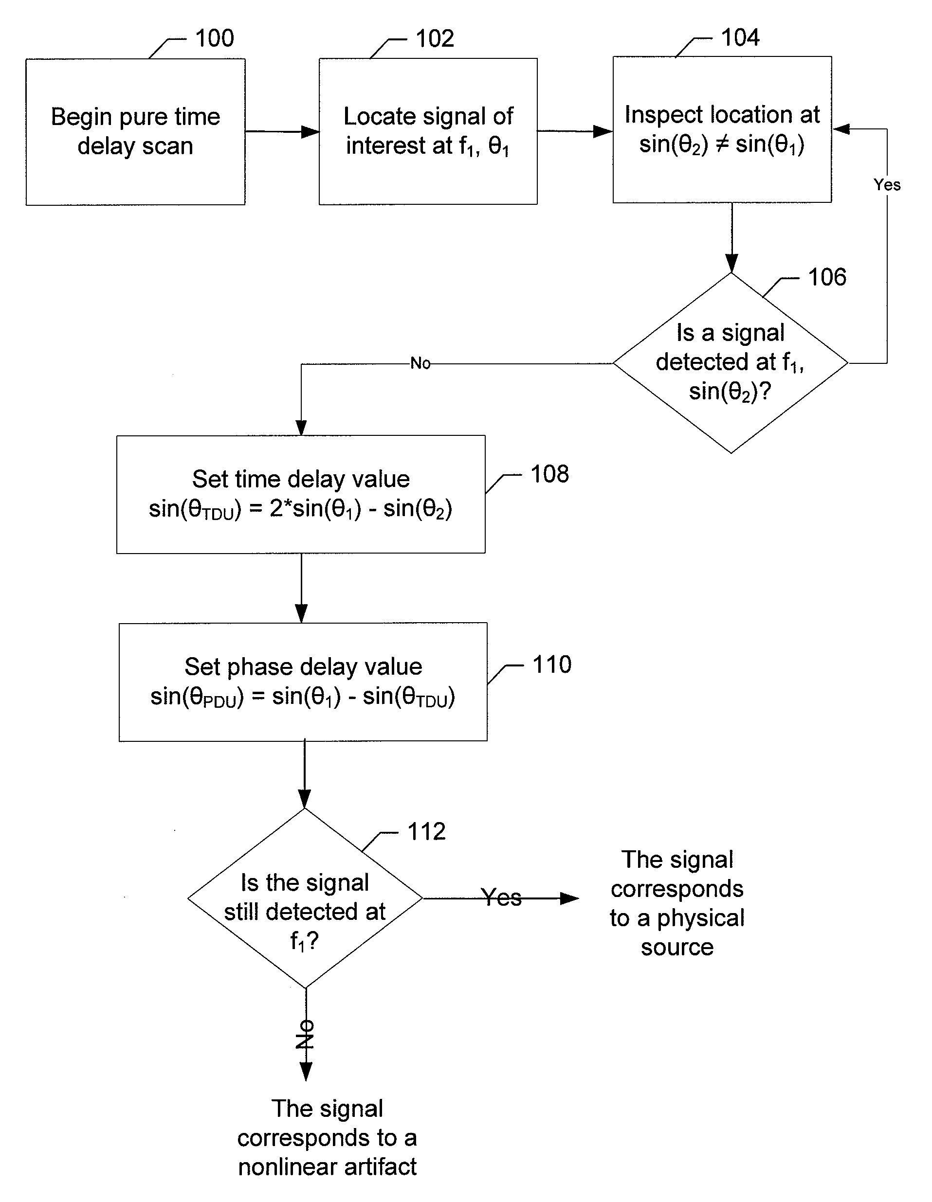
Method, Computer Program Product and System for Differentiating Physical Sources from Second Order Nonlinear Signal Effects
a nonlinear signal and physical source technology, applied in direction finders, antennas, instruments, etc., can solve the problems of rotating radars, inability to use entire apparatuses, and inability to achieve full scanning rate, so as to increase system cost, complexity and power consumption, system capabilities may be enhanced, and the effect of increasing system cos
- Summary
- Abstract
- Description
- Claims
- Application Information
AI Technical Summary
Benefits of technology
Problems solved by technology
Method used
Image

Examples
Embodiment Construction
[0024]Embodiments of the present inventions now will be described more fully hereinafter with reference to the accompanying drawings, in which some, but not all embodiments of the inventions are shown. Indeed, these inventions may be embodied in many different forms and should not be construed as limited to the embodiments set forth herein; rather, these embodiments are provided so that this disclosure will satisfy applicable legal requirements. Like reference numerals refer to like elements throughout.
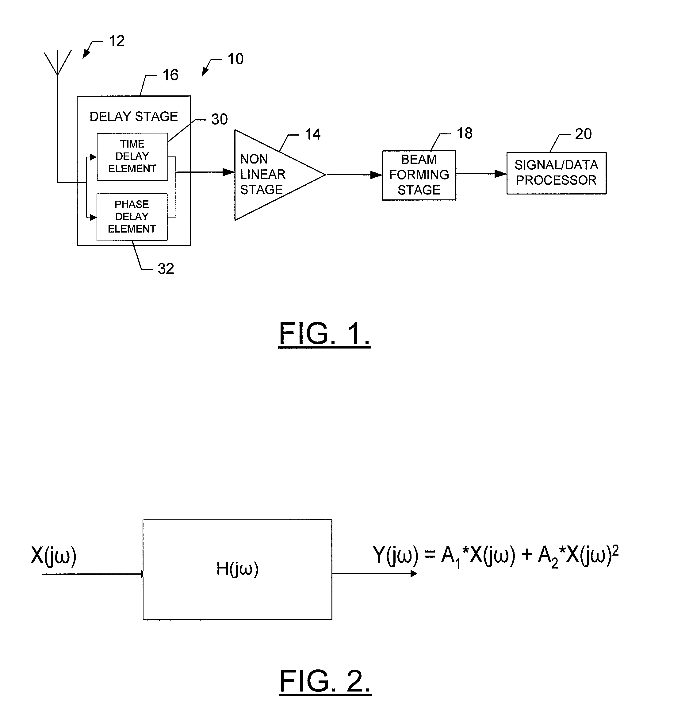
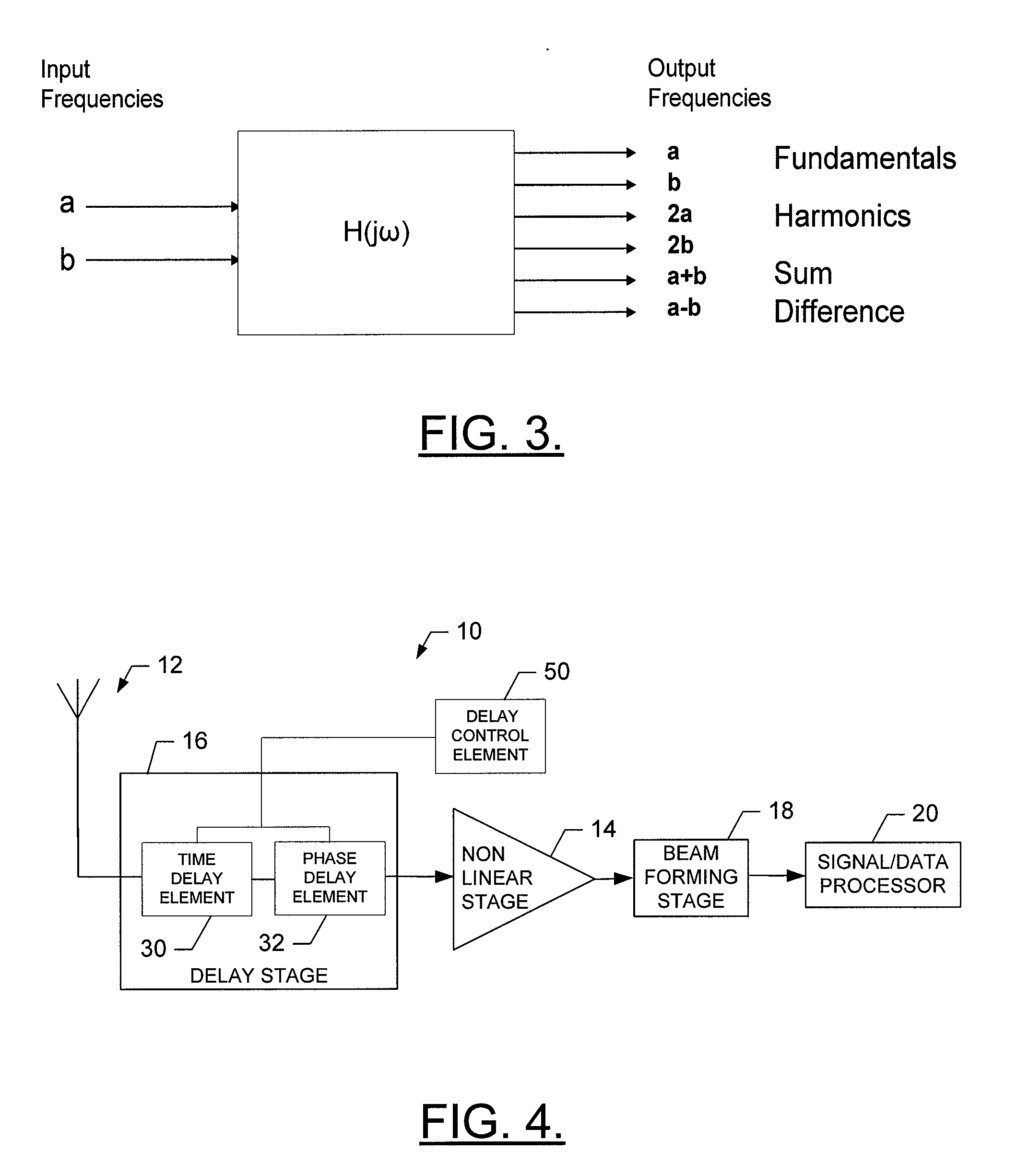
[0025]FIG. 1 is a basic block diagram illustrating a portion of a receive chain of an exemplary wideband receive only ESA, which will be referred to hereinafter as a wideband ESA 10. As shown in FIG. 1, the receive chain of the wideband ESA 10 generally includes an array 12, a nonlinear stage 14, a delay stage 16, a beamforming stage 18 and a signal / data processor 20. It should be noted that each of the array 12, the nonlinear stage 14, and the delay stage 16 may include multiple sub ...
PUM
 Abstract
Description
Claims
Application Information
 - R&D
- Intellectual Property
- Life Sciences
- Materials
- Tech Scout
- Unparalleled Data Quality
- Higher Quality Content
- 60% Fewer Hallucinations
Browse by: Latest US Patents, China's latest patents, Technical Efficacy Thesaurus, Application Domain, Technology Topic, Popular Technical Reports.
© 2025 PatSnap. All rights reserved.Legal|Privacy policy|Modern Slavery Act Transparency Statement|Sitemap|About US| Contact US: help@patsnap.com