
Mobile object tracking system

a tracking system and object technology, applied in the field of object tracking and control systems, can solve the problems of system inability to determine if any of the checked out keys were actually used and if, how long

Inactive Publication Date: 2007-04-10
KEY CONTROL HLDG
View PDF119 Cites 33 Cited by
  • Summary
  • Abstract
  • Description
  • Claims
  • Application Information

AI Technical Summary

Benefits of technology

"The present invention is a mobile object tracking system that is used to track the use of individual objects, such as keys, in a group of objects. The system includes a system controller, a mobile object tracking carrier, and a storage unit. The system controller records, processes, and reports usage information for the objects. The mobile object tracking carrier has guides for holding keys and is locked using a locking mechanism. The keys are attached to an identification tag, which is then scanned when the keys are used or replaced. The system can track which keys have been removed from the carrier and used, and can also track the movement of the carrier and the keys inside the storage unit. The invention provides a more efficient and effective way to track and manage keys and other objects."

Problems solved by technology

Obviously, such a manual system of tracking has numerous shortcomings due in large part to the very real potential of human error and forgetfulness in carrying out the sign-in and sign-out procedures and the inability to monitor how long the keys are out of the storage repository and who has the keys.
For example, currently, the system is unable to determine if any of the checked out keys was actually used and if so, for how long.
However, currently it is difficult lo track which specific ones of the keys of such a group or set were actually used while checked out and if so, for how long.

Method used


Image

  • Mobile object tracking system
  • Mobile object tracking system
  • Mobile object tracking system

Examples


Embodiment Construction

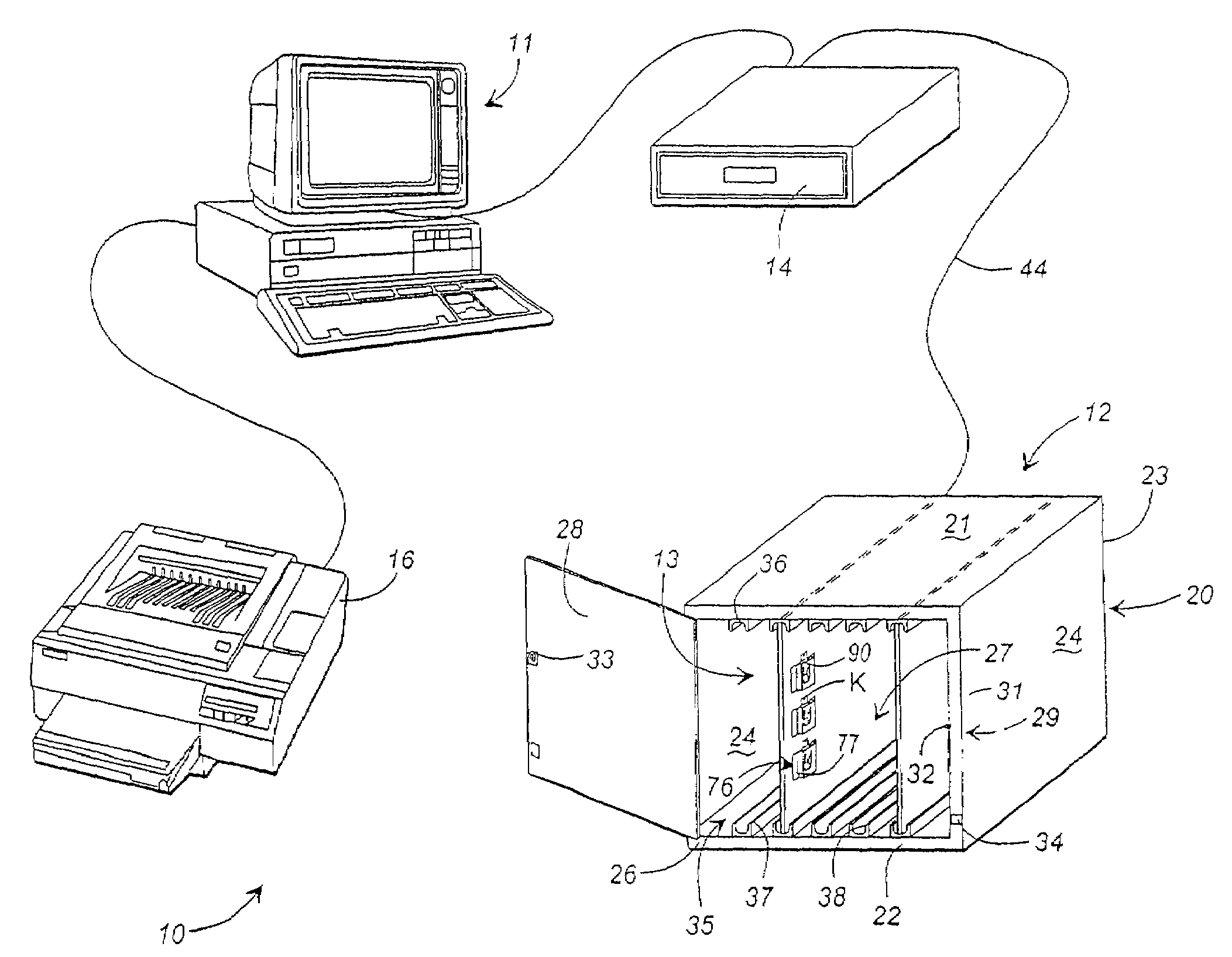
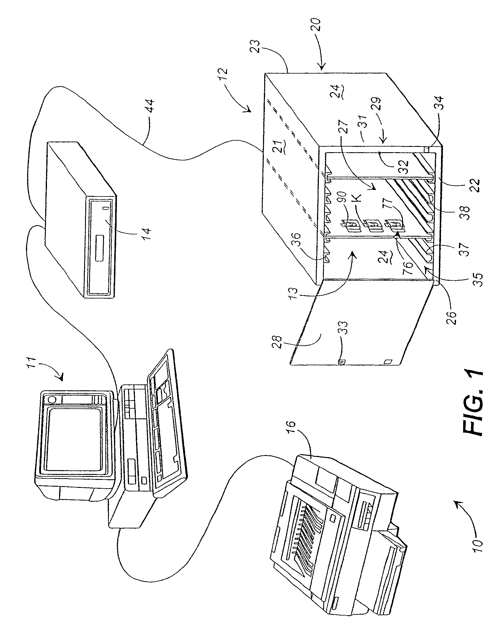
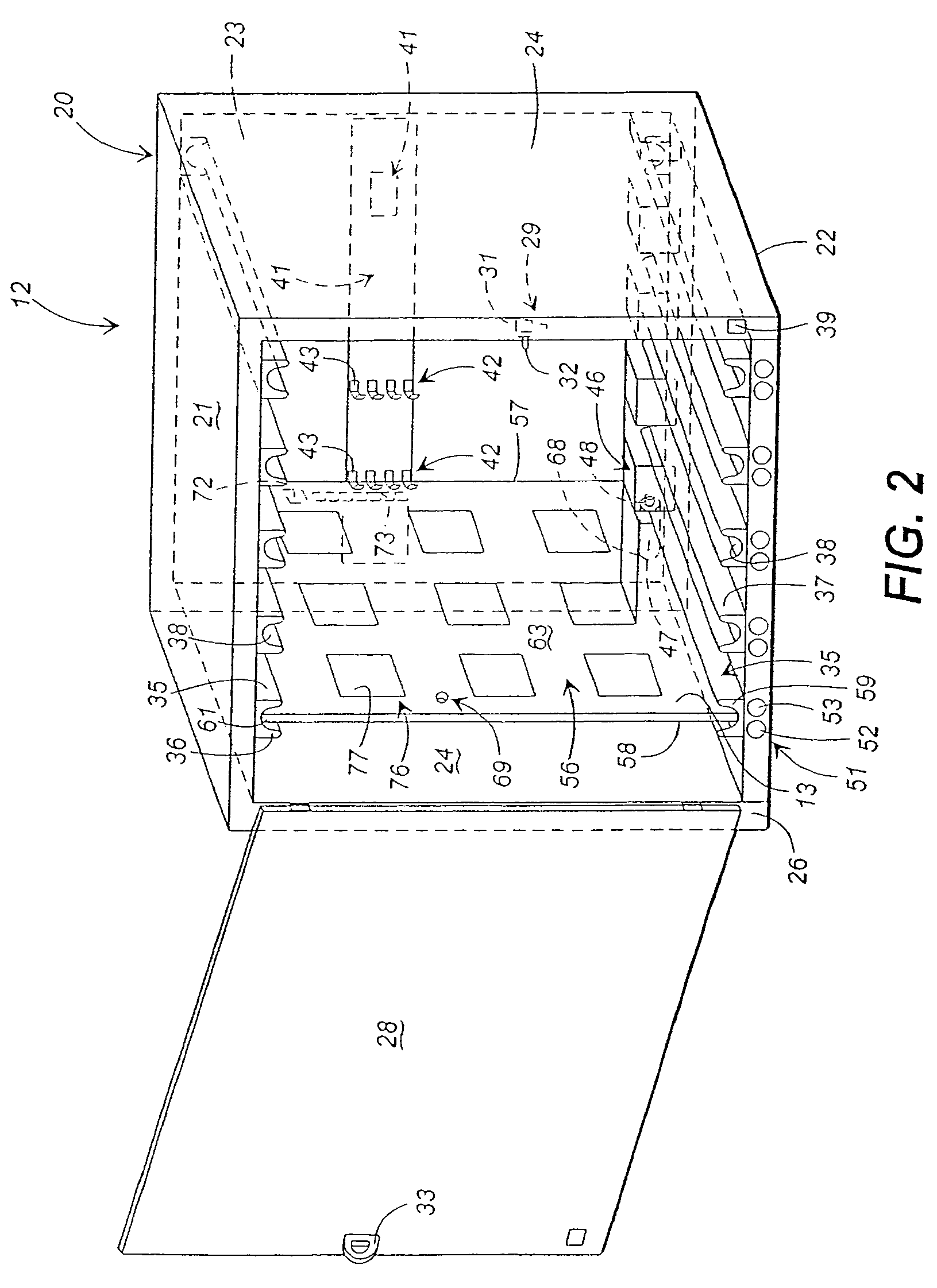
[0036]Referring now to the drawings in greater detail in which like numerals indicate like parts throughout the several views, FIG. 1 generally illustrates a mobile object tracking system 10 for use in tracking individual objects such as keys, i.e. for vehicles, vaults, etc., checked out in groups or sets of objects. The system will be especially useful for applications where it is necessary for the keys or other objects being tracked to be checked out in groups such as for armored car routes where multiple stops are made, requiring multiple keys to provide monitoring and tracking of use of the individual keys of each checked out or accessed set or group of keys.

[0037]It will be understood by those skilled in the art that while the mobile object tracking system of the present invention is disclosed in greater detail below with reference to use in tracking keys, it is possible to utilize the present invention for tracking a variety of objects other than keys as desired, and the discl...


PUM


Abstract

A mobile object tracking system is provided for tracking the removal and use of specific objects within a group checked out from storage between the time the objects are checked out and the replacement of the objects in the storage. The system includes a system controller and a storage unit that receive and store a series of object carriers therein. Each object carrier includes a series of object holders in which id tags for the group of objects checked out of the storage are received. The object carrier monitors the time each object is removed from the object carrier, which information is thereafter communicated to the system controller.

Description

REFERENCE TO RELATED APPLICATIONS[0001]This application is a continuation of U.S. patent application Ser. No. 10 / 614,387, filed on Jul. 7, 2003, now abandoned; which application is a continuation of U.S. patent application Ser. No. 10 / 074,163, filed on Feb. 12, 2002, now abandoned; which is a continuation of U.S. patent application Ser. No. 09 / 974,158, filed on Oct. 9, 2001, now U.S. Pat. No. 6,424,260; which is a continuation of U.S. patent application Ser. No. 09 / 782,070 filed on Feb. 12, 2001, now U.S. Pat. No. 6,392,543; which is a continuation of U.S. patent application Ser. No. 09 / 392,175, filed on Sep. 9, 1999, now U.S. Pat. No. 6,232,876; which application claims the benefit of the filing date of prior filed U.S. Provisional Patent Application Ser. No. 60 / 099,954 filed Sept. 11, 1998.TECHNICAL FIELD[0002]This invention relates generally to object tracking and control systems and more particularly to systems for tracking and controlling access to and disposition of trackable ...

Claims


Application Information

Patent Timeline
Patent Type & Authority Patents(United States)
IPC IPC(8): G08B13/14G06K17/00G06T15/02G07B15/02G07B15/04G08B13/24
CPCG06K17/00G07B15/04G08B13/1427G08B13/1454G08B13/1463G08B13/2417G08B13/2431G08B13/2434G08B13/2448G08B13/2462G08B13/2471G08B13/2474G08B13/2477G08B13/2482G08B21/0227G08B21/0286G08B21/0288G06K2017/0045
Inventor MALONEY, WILLIAM C.
Owner KEY CONTROL HLDG
Learn More