
Drum vent

Inactive Publication Date: 2007-04-10
ENTEGRIS INC
View PDF23 Cites 25 Cited by
  • Summary
  • Abstract
  • Description
  • Claims
  • Application Information

AI Technical Summary

Benefits of technology

[0013]The attachment of the membrane structure with the cross sealing bands or the inner sealing area or both as well as at the sealing band surrounding the vent openings offers significant advantages over prior art devices, relative to strength and durability. First, the additional attachment contact area allows force applied to the membrane structure to be spread over a larger area. The result is reduced stress values at the sealing band during drop testing and other high load causing events. As a consequence, the likelihood that membrane assembly will be torn loose or ruptured during such events is reduced. Also, the resultant overall reduction in unsupported span of vent membrane assembly results in less deflection of the membrane during such conditions. The described structure also enables the use of generally thinner membrane structures with greater spacing between the membrane structure and any protective structure, thereby improving the effectiveness and performance of the venting device.

Problems solved by technology

The result is reduced stress values at the sealing band during drop testing and other high load causing events.

Method used


Image

  • Drum vent
  • Drum vent
  • Drum vent

Examples


Embodiment Construction

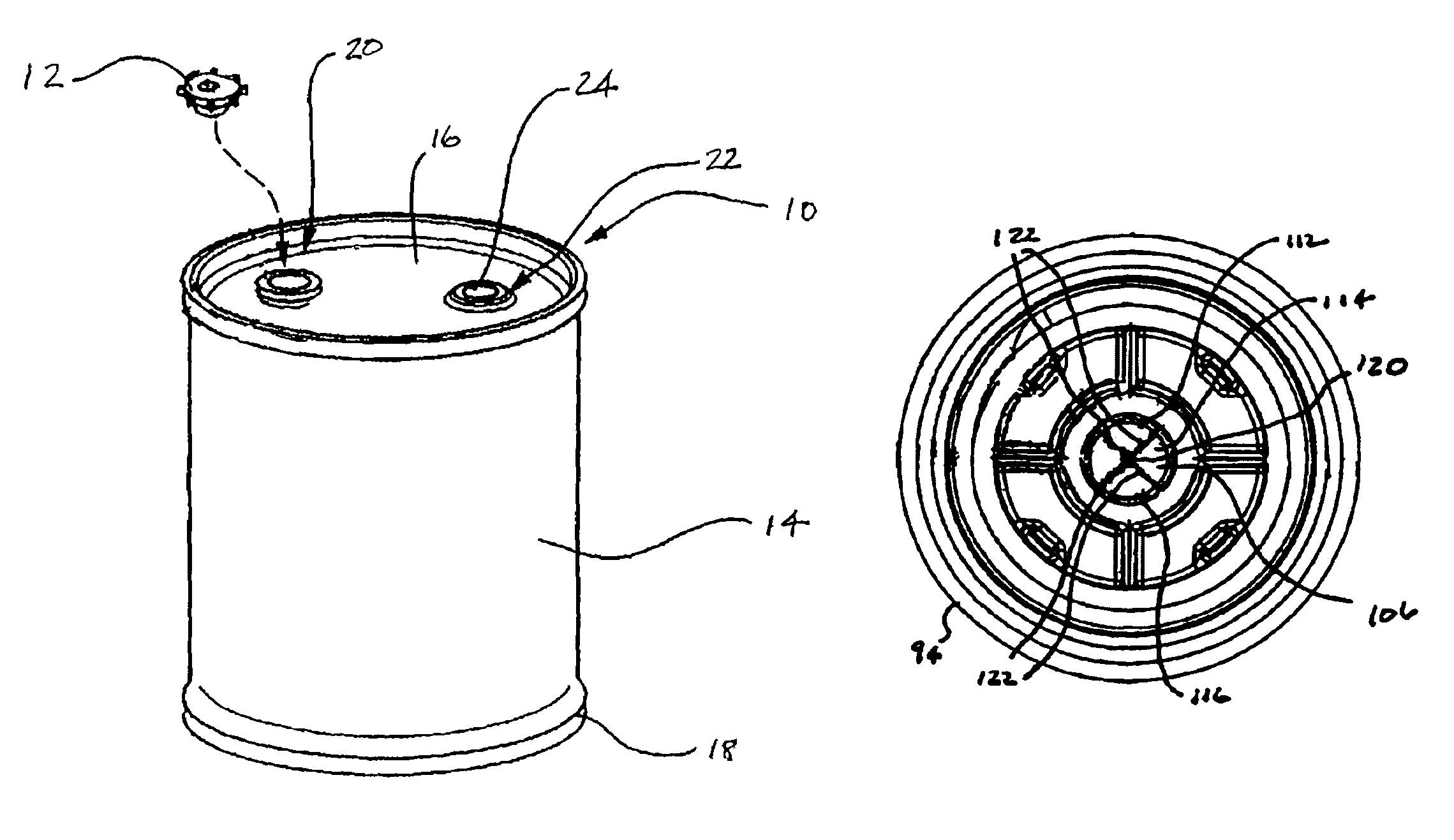
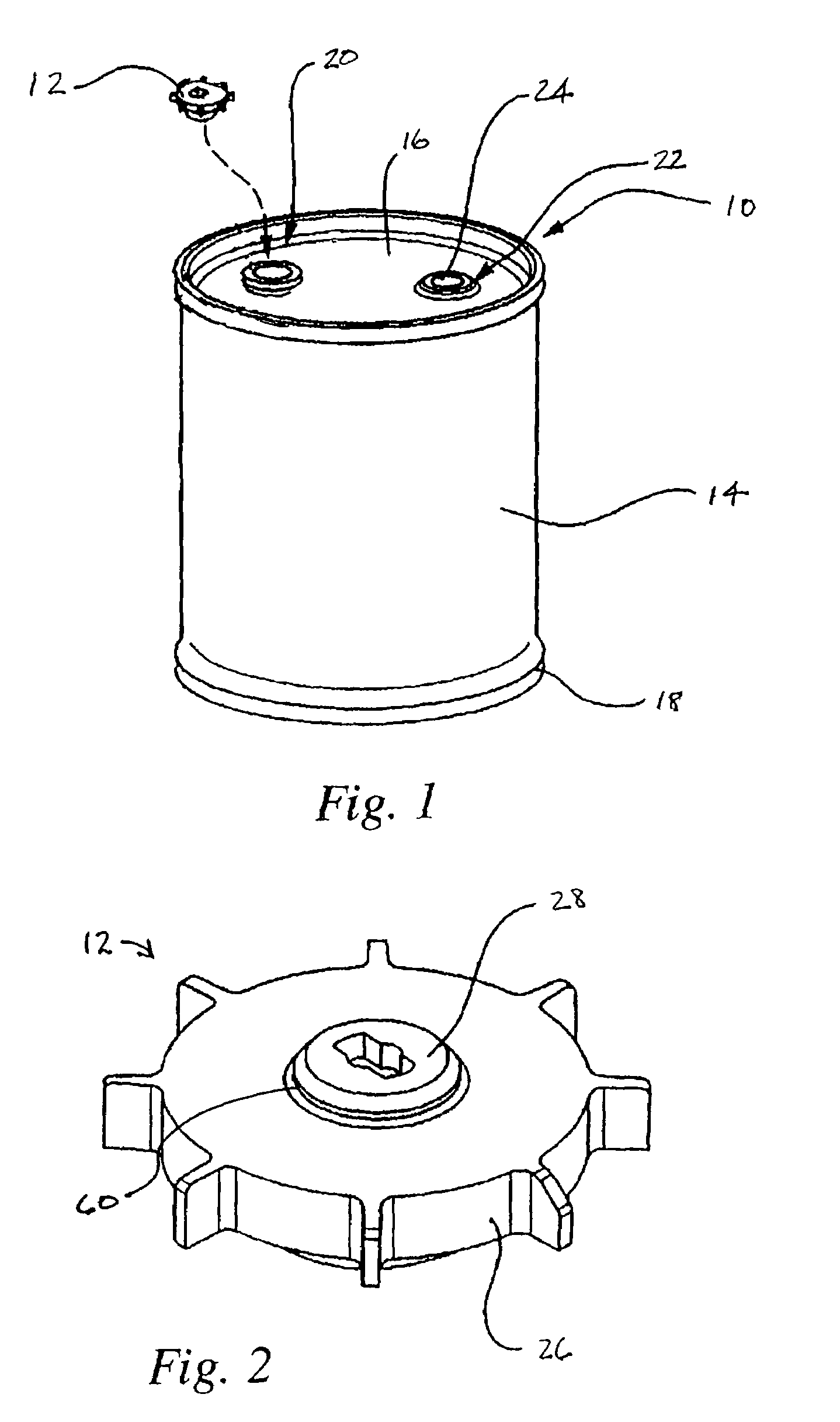
[0029]Referring to FIGS. 1 and 2, a drum 10 and vented closure 12 according to the present invention is depicted. FIG. 1 depicts in perspective a plastic blow molded drum 10 generally including a cylindrical wall portion 14, a top structure 16 and a bottom structure 18. Top structure 16 includes a first bunghole 20 and a second bunghole 22. Second bunghole is closed with a standard bung 24 which sealingly engages in second bunghole 22. Vented closure 12 sealingly engages in first bunghole 20. First and second bungholes 20, 22, generally have interior threads which threadedly and sealingly engage exterior threads on vented closure 12 and standard bung 24. It will be appreciated, however, that closure 12 and bung 24 may be engaged in bungholes 20, 22, by any alternative means as may be known to those of skill in the art.

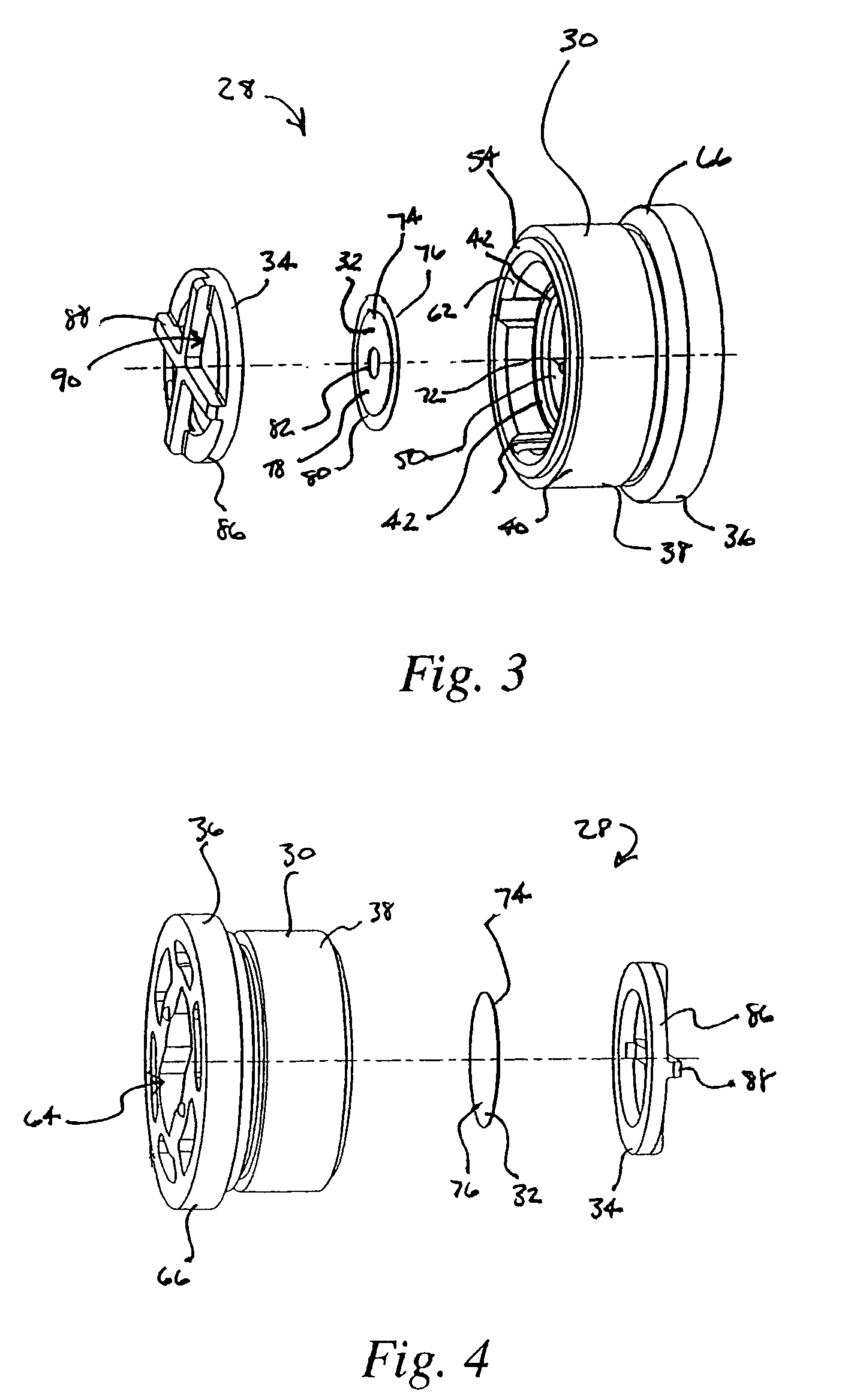
[0030]Vented closure 12 is depicted in perspective view in FIG. 2. Closure 12 generally includes bung portion 26 and venting device 28. Venting device 28, as depicted ...


PUM


Abstract

A venting device for a drum. The venting device includes a body having a pair of opposing sides and defining a plurality of vent passages. The vent passages extend through the body and each an opening at each of the pair of opposing sides. The vent passages are spaced apart and arranged around a center portion of the body. A membrane structure is positioned so as to cover the openings of the vent passages on one of the pair of opposing sides of the body. The membrane structure is sealingly affixed to the body portion in an outer sealing band surrounding the openings of the vent passages. The membrane structure may be further affixed with one or more cross sealing bands extending across the membrane. A portion of the membrane structure may be further affixed to the center portion of the body. A protective structure may be attached to the body and positioned over the membrane structure.

Description

RELATED APPLICATIONS[0001]This application is a Continuation-in-Part of application Ser. No. 10 / 696,574, entitled DRUM VENT, by Dale Maenke, filed Oct. 29, 2003 now U.S. Pat. No. 6,883,675 which in turn claims benefit of U.S. Provisional Appl. No. 60 / 422,433, entitled VENT PLUG, by Dale Maenke, filed Oct. 30, 2002. Both of the aforesaid applications are hereby fully incorporated herein by reference.FIELD OF THE INVENTION[0002]The present invention is directed to venting of drums, and more particularly to a venting device for a drum.BACKGROUND OF THE INVENTION[0003]Drums, barrels and other containers are widely used to store, transport and dispense chemicals and industrial fluids. An example of such a drum is disclosed in U.S. Pat. No. 6,045,000, which is owned by the owners of the present invention and is hereby fully incorporated herein by reference. In some industries, such as semiconductor processing, the liquids contained may be highly volatile and may evolve vapors or gases tha...

Claims


Application Information

Patent Timeline
IPC IPC(8): B65D51/16B65D85/84
CPCB65D7/045B65D51/1644B65D85/84
Inventor MAENKE, DALE
Owner ENTEGRIS INC
Learn More