Automated sampling device

a sampling device and automatic technology, applied in the field of laboratory instruments, can solve the problems of dust, dust, or the like, falling into these containers as additional sources of sample contamination,

Active Publication Date: 2007-04-10
ELEMENTAL SCI
View PDF25 Cites 15 Cited by
  • Summary
  • Abstract
  • Description
  • Claims
  • Application Information

AI Technical Summary

Benefits of technology

The present invention is an automated sampling device that eliminates possible sample contamination by contaminants falling into the sample vessels during analysis. The device includes a support surface for holding a sample holder, a sample arm assembly for supporting a sample probe, and a drive assembly for powering and positioning the sample arm assembly. The sample arm assembly can move in translation and radially about the z-axis for inserting and removing the sample probe. The device can also be mounted on wheels for easy preparation of samples at a separate location. The technical effects of the invention are improved accuracy and reliability of sample analysis and reduced risk of contamination.

Problems solved by technology

Although autosamplers presently known in the art have greatly increased the ease and efficiency of assaying multiple samples at a given time, such samplers are disadvantageous in that they are likely to introduce an additional source for sample contamination, allowing for contamination of sample vessels by contaminants which may fall into containers during analysis.
Present autosamplers employing mechanical parts which may cause dust, or the like, to fall into these containers because of mechanical wear of the devices that either is directly above the containers while they are moving or as the containers themselves move underneath a dispensing pipette.

Method used


Image

  • Automated sampling device
  • Automated sampling device
  • Automated sampling device

Examples


Embodiment Construction

[0026]Reference will now be made in detail to the presently preferred embodiments of the invention, examples of which are illustrated in the accompanying drawings.

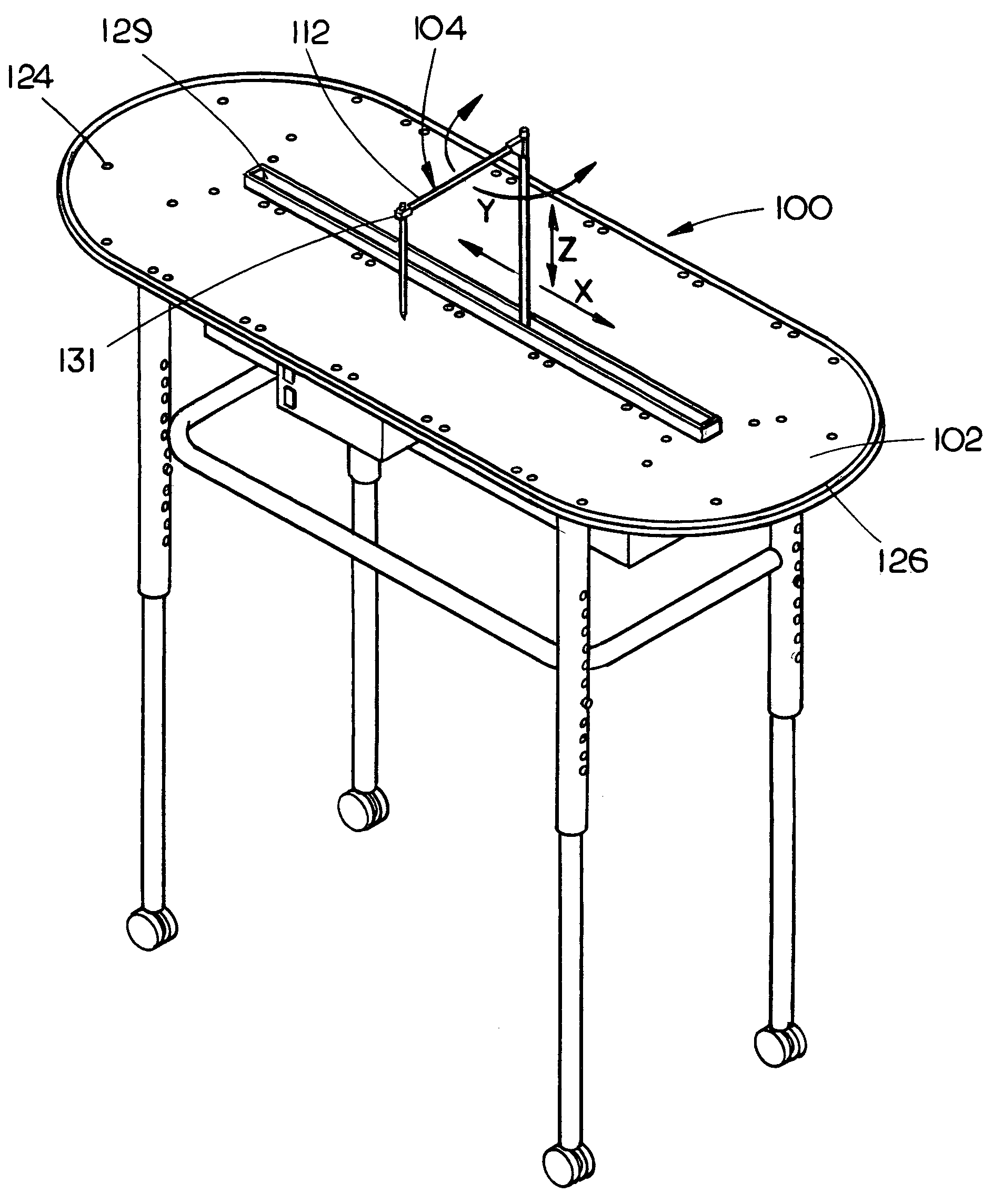
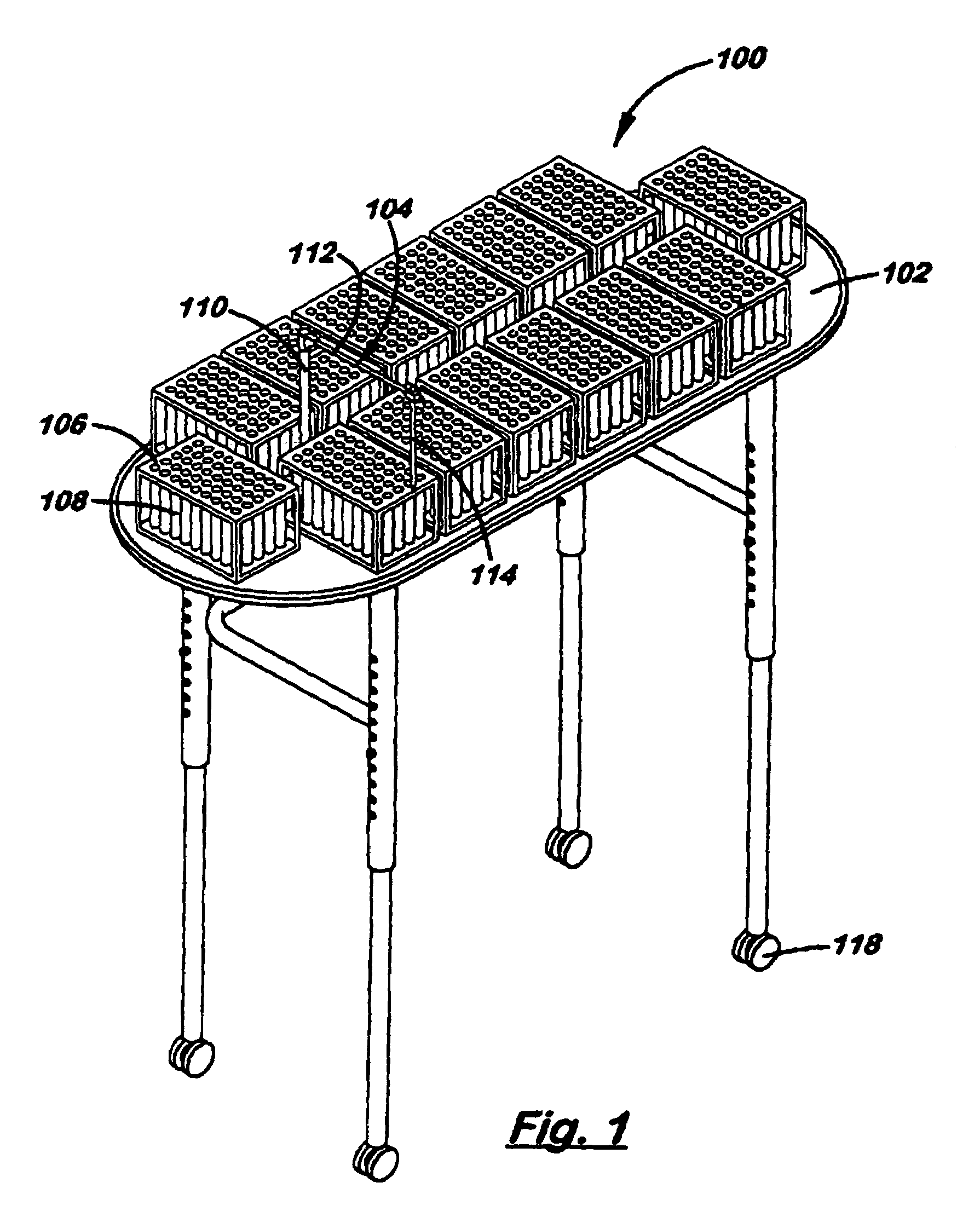
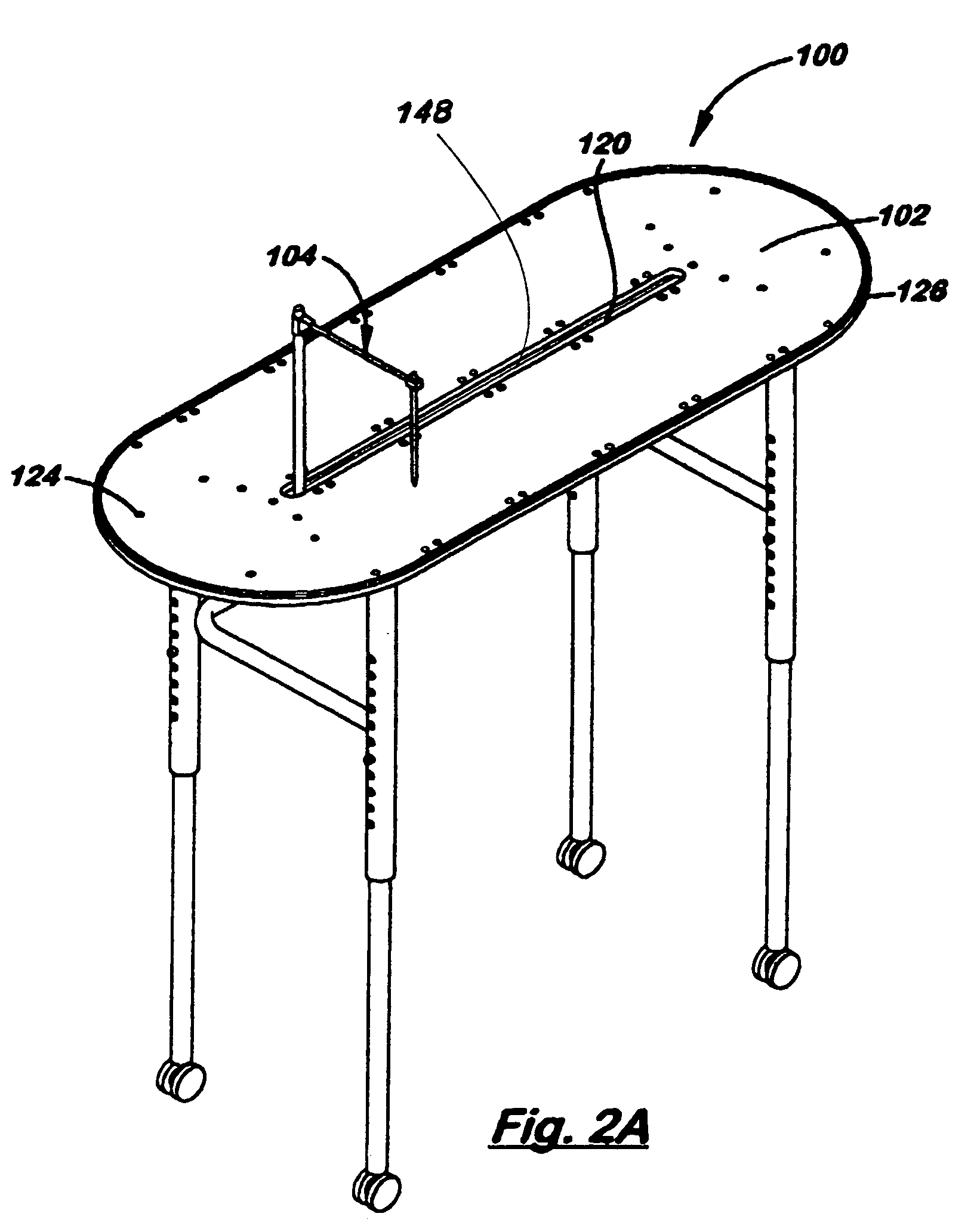
[0027]FIG. 1 illustrates automated sampling device 100 in accordance with an exemplary embodiment of the present invention. Automated sampling device 100 includes table top 102 and sample arm assembly 104. Further, sample holders 106 holding multiple sample vessels 108 are present on table top 102 in preparation for sample assaying. It should be understood that automated sampling device 100 may assay from one to many hundreds of samples (e.g., greater than 1200 samples in the exemplary embodiment illustrated) in a given time depending upon test requirements.

[0028]In the embodiment illustrated, sample arm assembly 104 includes a z-axis support 110 and a sample probe support arm 112 that supports a sample probe 114. As illustrated, the z-axis which is aligned with gravity or vertical axis. In use, sample probe 114 is mounted...


PUM

PropertyMeasurementUnit
lengthaaaaaaaaaa
purityaaaaaaaaaa
timeaaaaaaaaaa

Abstract

The present invention is directed to an automated sampling and / or dispensing device for minimizing possible sample contamination from contaminants (e.g., mechanical pieces of machinery, dust, or the like) falling into sample vials during analysis by having no mechanical moving parts above stationary samples. The automated sampling or dispensing device may include a table for supporting a sample holder holding a sample vessel, a sample arm assembly extending for supporting a sample probe, the sample arm assembly including a z-axis support and a sample probe support arm, and a drive assembly couple to the z-axis support of the sample arm assembly for powering and positioning the sample arm assembly. The drive assembly causes the sample arm assembly to move in translation along the x-axis, in translation along an axis coaxial with the z-axis support, and radially about the z-axis for inserting the sample probe into the sample vessel.

Description

CROSS REFERENCE[0001]The present application claims priority to U.S. Provisional Patent Ser. No. 60 / 604,548, entitled: Automated Sampling Device, filed on Aug. 26, 2004 which is hereby incorporated in its entirety.FIELD OF INVENTION[0002]The present invention relates generally to laboratory instrumentation, particularly automated sampling devices for drawing samples from stationary sample vessels, and more specifically, to an automated sampling device having a sample arm capable of three-axis movement with no mechanically wearing parts positioned above the stationary samples.BACKGROUND OF THE INVENTION[0003]In many laboratory settings, it is often necessary to analyze a large number of chemical or biochemical samples at one time. In order to stream-line such processes, the manipulation of samples has been mechanized. Such mechanized sampling is commonly referred to as autosampling and is performed using an automated sampling device or autosampler.[0004]While a vast array of autosamp...

Claims


Application Information

Patent Timeline
Patent Type & Authority Patents(United States)
IPC IPC(8): G01N1/00
CPCG01N35/0099G01N35/04
Inventor WIEDERIN, DANDIAZ, DAVIDBARRETT, GARY
Owner ELEMENTAL SCI
Why Eureka
Try Eureka