
Method of predicting the on-set of formation solid production in high-rate perforated and open hole gas wells

a gas well and perforation technology, applied in the field of completion of gas wells, can solve the problems of increasing completion costs, affecting the integrity of surface and downhole equipment, and posing extreme safety hazards

Inactive Publication Date: 2007-04-03
BAKER HUGHES INC
View PDF9 Cites 27 Cited by
  • Summary
  • Abstract
  • Description
  • Claims
  • Application Information

AI Technical Summary

Benefits of technology

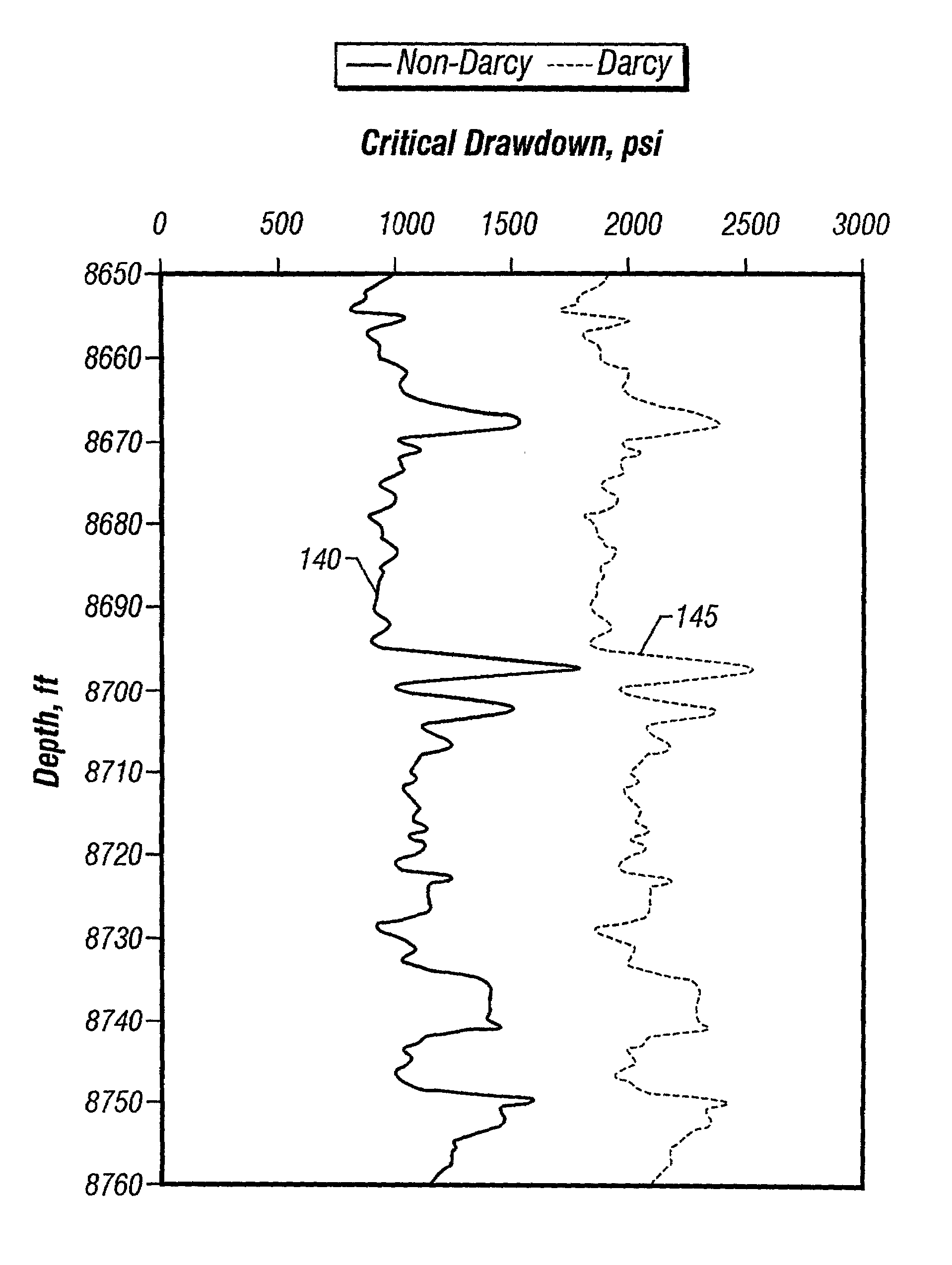
The patent describes a method for predicting the maximum pressure allowed in high-rate gas wells. This method uses a continuous profiling of critical drawdown with depth to quickly identify potential sand producing zones and determine the maximum flow rates. Both spherical and cylindrical models are used, with the cylindrical model being suitable for horizontal open-hole completions. The method takes into account static reservoir mechanical properties and strength, as well as the cohesive strength and internal friction angle of the rock formation. The data is input into an analytical model to determine the critical drawdown pressure on a predetermined interval basis. The method can also be used with experimental core results to predict the static rock mechanical properties.

Problems solved by technology

Because of the high gas velocity in the production tubing, any sand production associated with this high velocity can be extremely detrimental to the integrity of surface and downhole equipment and pose extreme safety hazards.
The unnecessary application of sand control techniques, as a precaution against anticipated sand production, can cause an increase in completion costs and a possible reduction in well productivity.
However, if operating conditions dictate the need for sand exclusion, such techniques can make a well, which otherwise could have been abandoned or not developed, extremely profitable.
Tensile failures predominate in unconsolidated sands and compressive failures in consolidated sandstone.
Because this tensile model assumes only Darcy's flow regime, its use is limited to low-rate gas well applications.

Method used


Image

  • Method of predicting the on-set of formation solid production in high-rate perforated and open hole gas wells
  • Method of predicting the on-set of formation solid production in high-rate perforated and open hole gas wells
  • Method of predicting the on-set of formation solid production in high-rate perforated and open hole gas wells

Examples


application example

Horizontal Well

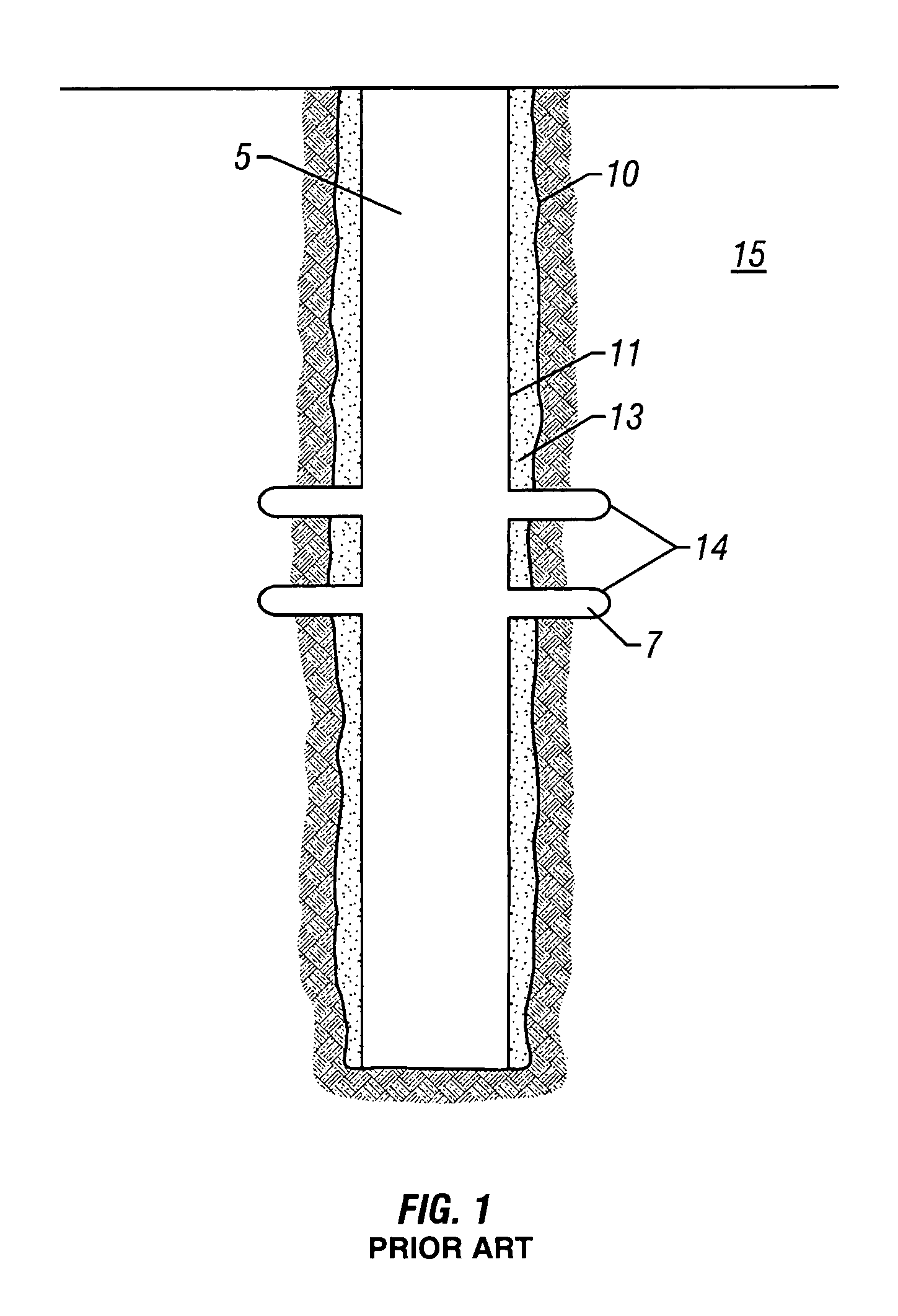
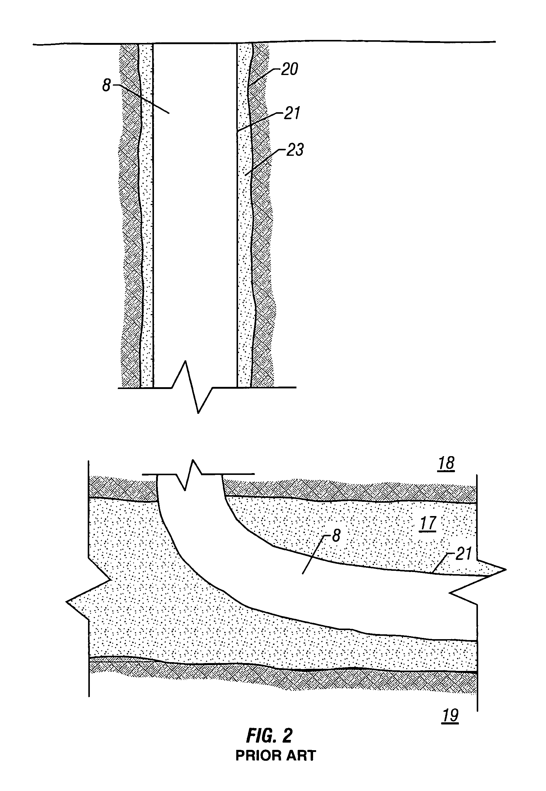
[0062]Horizontal and multilateral wells are fast becoming an industry standard for wellbore construction. Among the preferred completion methods for most horizontal wells are open-holes whose sand control consists of either slotted liners of pre-pack screens. For such a completion in a weak but competent formation, the bottomhole flowing pressure must be ascertained to stay above the value dictated by the formation's critical drawdown pressure, in order to minimize the potential of sand failure. The cylindrical cavity model (CDP-OH) can be used, assuming that the well is located in a homogeneous reservoir of height H and bounded by impermeable layers, as shown in FIG. 10. For such a configuration, the flow will be cylindrically symmetric up to the radial distance of roughly H / 2 and becomes uniform with increasing distance (>H / 2) from the wellbore: see Ramos, G. G., Katahara, K. W., Gray, J. D., and Knox, D. J. W.: “Sand Production in Vertical and Horizontal Wells in a...


PUM


Abstract

A method for predicting the on-set of sand production or critical drawdown pressure (CDP) in high flow rate gas wells. The method describes the perforation and open-hole cavity stability incorporating both rock and fluid mechanics fundamentals. The pore pressure gradient is calculated using the non-Darcy gas flow equation and coupled with the stress-state for a perfectly Mohr-Coulomb material. Sand production is assumed to initiate when the drawdown pressure condition induces tensile stresses across the cavity face. Both spherical and cylindrical models are presented. The spherical model is suitable for cased and perforated applications while the cylindrical model is used for a horizontal open-hole completion.

Description

BACKGROUND OF THE INVENTION[0001]1. Field of the Invention[0002]This invention relates generally to the completion of gas wells and more particularly to a method of predicting the on-set of solids production in high flow rate gas wells.[0003]2. Description of the Related Art[0004]High-rate gas well completions are common practice in offshore developments and among some of the most prolific gas fields in the world. These fields typically have reservoirs that are highly porous and permeable but weakly consolidated or cemented, and sand production is a major concern. Because of the high gas velocity in the production tubing, any sand production associated with this high velocity can be extremely detrimental to the integrity of surface and downhole equipment and pose extreme safety hazards. Prediction of a maximum sand free production rate is therefore critical, not only from a safety point of view but also economically. The unnecessary application of sand control techniques, as a preca...

Claims


Application Information

Patent Timeline
Patent Type & Authority Patents(United States)
IPC IPC(8): G06G7/48E21B47/01G01V1/40E21B47/00
CPCE21B47/00E21B49/0875
Inventor ONG, SEE HONGRAMOS, GANGERICO G.ZHENG, ZIQIONG
Owner BAKER HUGHES INC
Learn More