Image display apparatus and image display system
a technology of image display and display device, which is applied in the field of image display device, can solve the problems of high cost, difficult to realize a larger field angle, and the inability to increase the interpupillary distance ipd between the pupils of the optical system for left and right eyes, and achieves the effect of reducing cost, compact size and large field angl
- Summary
- Abstract
- Description
- Claims
- Application Information
AI Technical Summary
Benefits of technology
Problems solved by technology
Method used
Image

Examples
embodiment 1
(Embodiment 1)
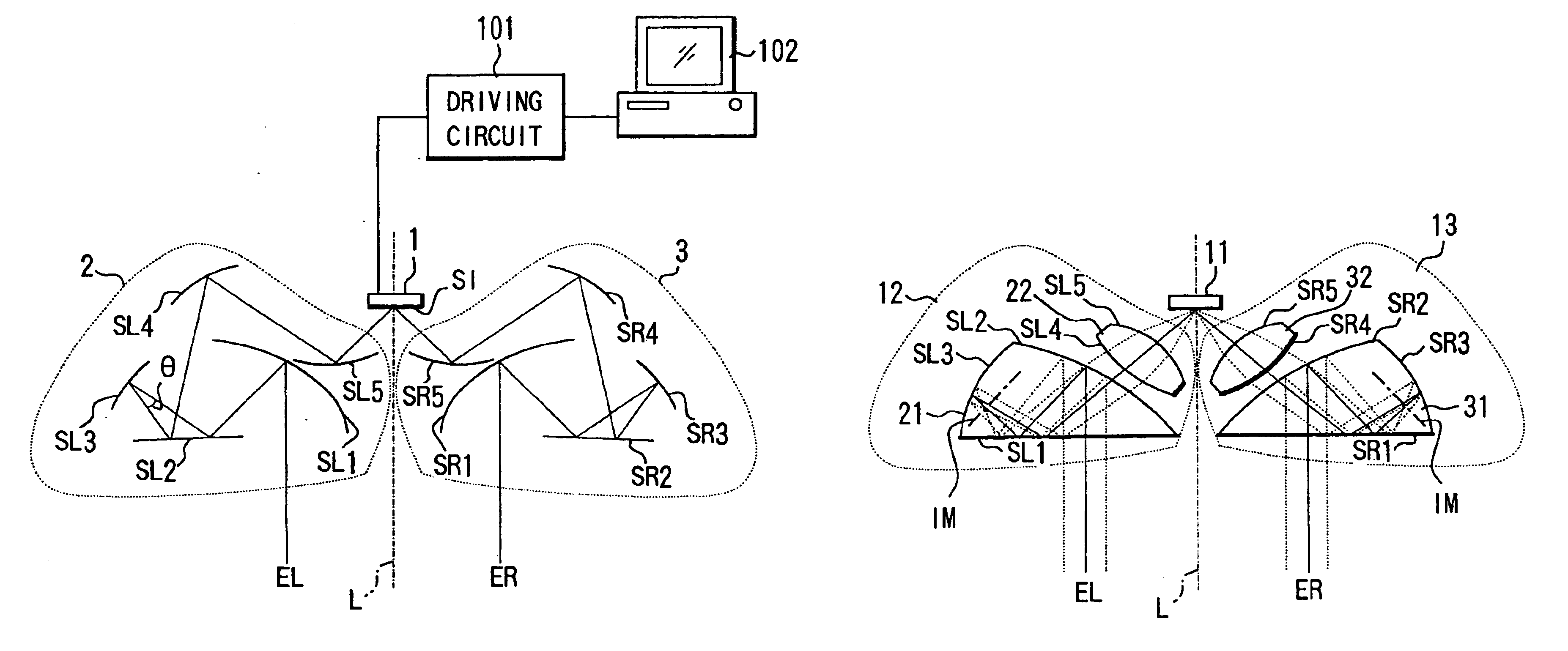
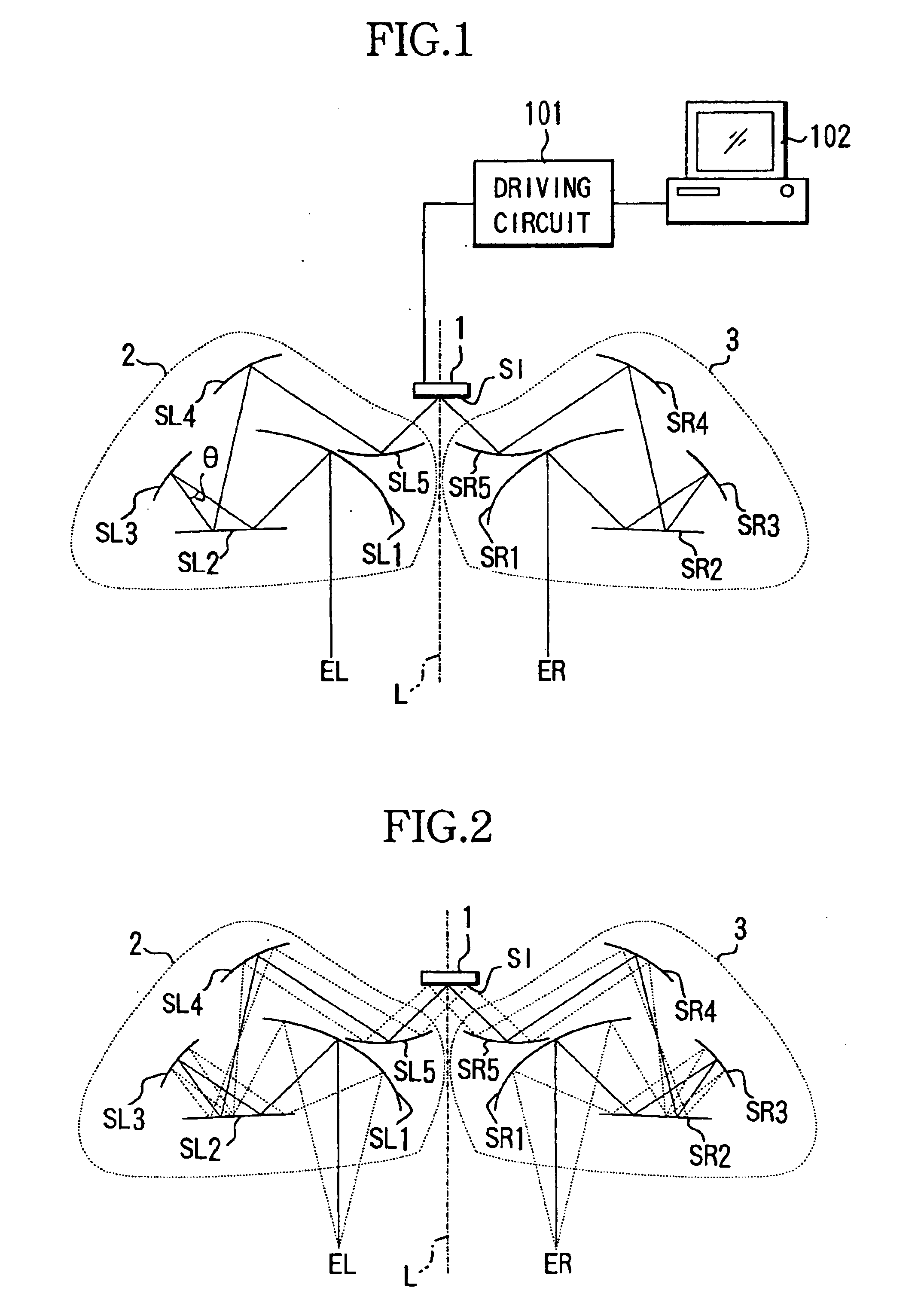
[0042]FIG. 1 shows the structure of main portions of a head mounted display serving as an image display apparatus which is Embodiment 1 of the present invention. In FIG. 1, reference numeral 1 shows a single image forming device which forms an original image and is realized by a CRT, an LCD, an electroluminescence device or the like.
[0043]A driving circuit 101 is connected to the image forming device 1. The driving circuit 101 is supplied with image information from an image information supply apparatus such as a personal computer, a television, a VCR, a DVD player, a reception antenna and a tuner, and drives the image forming device 1 to display an original image corresponding to the image information. The image information supply apparatus and the head mounted display constitute an image display system. This applies to Embodiments 2 and 3, although not shown.
[0044]EL shows a left eye (a pupil position) of an observer located at a desirable position, and ER shows a ri...
embodiment 2
(Embodiment 2)
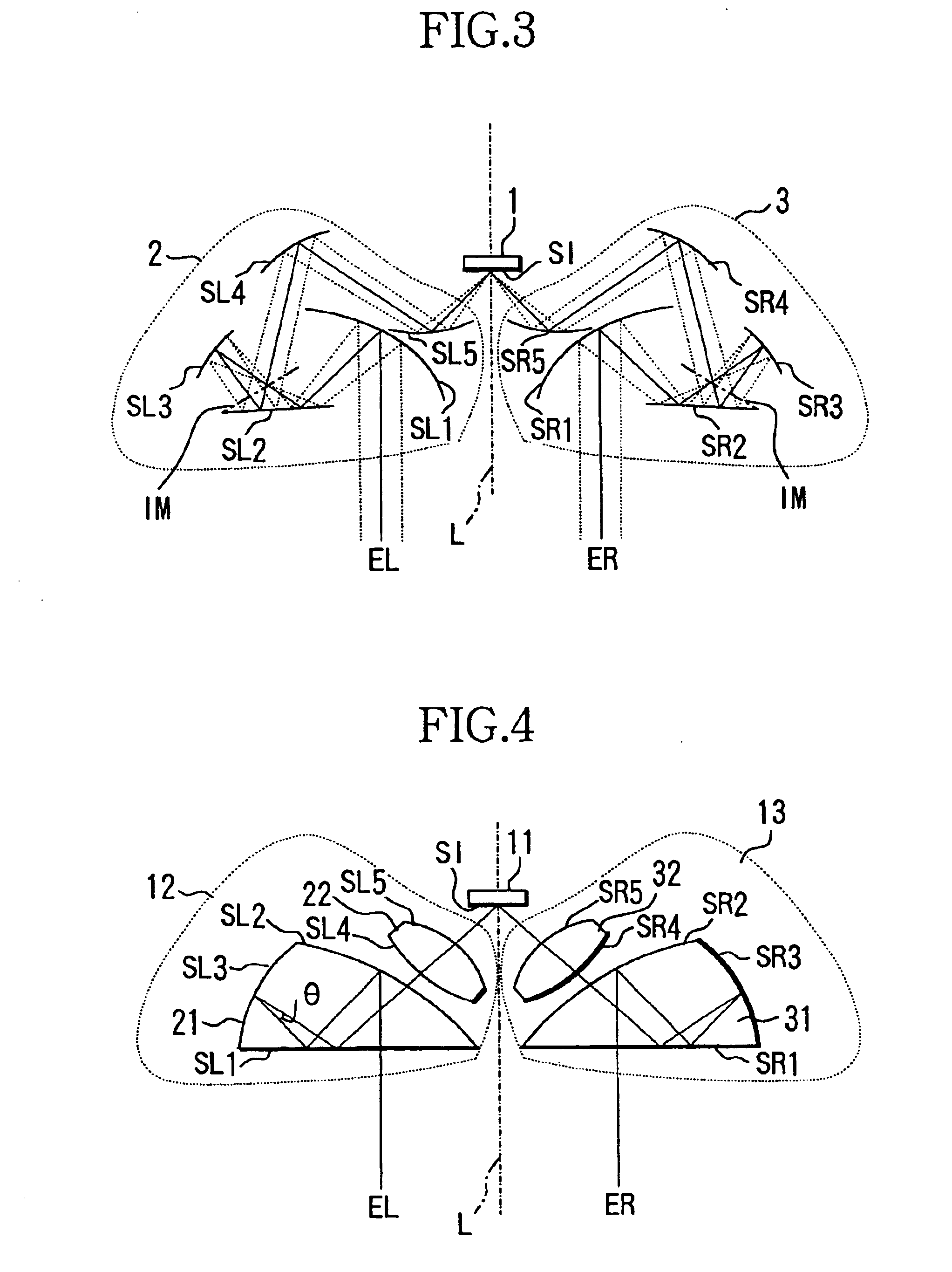
[0070]FIG. 4 shows the structure of main portions of a head mounted display which is Embodiment 2 of the present invention.
[0071]In FIG. 4, reference numeral 11 shows a single image forming device which forms an original image. EL shows a left eye (a pupil position) of an observer located at a desirable position, and ER shows a right eye (a pupil position) of the observer located at a desirable position.
[0072]Reference numeral 12 shows a left eye optical system (a first optical system). The left eye optical system 12 has a prism 21 which has three surfaces of a surface SL1, a surface SL2 having a semi-transmissive reflective film formed thereon, and a surface SL3 having a reflective film formed thereon. The optical system also has a lens 22 which has transmissive surfaces SL4 and SL5. These are arranged to guide light from an original image forming surface SI of the image forming device 11 to the left eye EL.
[0073]Reference numeral 13 shows a right eye optical system. ...
embodiment 3
[0105]FIG. 7 shows the structure of main portions of a head mounted display which is Embodiment 3 of the present invention. In FIG. 7, reference numeral 41 shows a single image forming device which forms an original image. EL shows a left eye (a pupil position) of an observer located at a desirable position, and ER shows a right eye (a pupil position) of the observer located at a desirable position.
[0106]Reference numeral 42 shows a left eye optical system(a first optical system). The left eye optical system 42 has a prism 53 which has three surfaces of a surface SL1 having a reflective film formed on at least a portion thereof, a surface SL2 having a semi-transmissive reflective film formed thereon, and a surface SL3 having a reflective film formed thereon. The optical system 42 also has a prism 54 which has the cemented surface SL2 t o the prism 53, a surface SL4 having a reflective film formed thereon, and a surface SL5 as a transmissive surface. These are arranged to guide light...
PUM
| Property | Measurement | Unit |
|---|---|---|
| angle | aaaaa | aaaaa |
| length | aaaaa | aaaaa |
| length | aaaaa | aaaaa |
Abstract
Description
Claims
Application Information
 - R&D
- Intellectual Property
- Life Sciences
- Materials
- Tech Scout
- Unparalleled Data Quality
- Higher Quality Content
- 60% Fewer Hallucinations
Browse by: Latest US Patents, China's latest patents, Technical Efficacy Thesaurus, Application Domain, Technology Topic, Popular Technical Reports.
© 2025 PatSnap. All rights reserved.Legal|Privacy policy|Modern Slavery Act Transparency Statement|Sitemap|About US| Contact US: help@patsnap.com