
Wheel for belted track vehicles

a technology for belted track vehicles and wheels, which is applied in the direction of wheel-axle combinations, transportation and packaging, hoisting equipment, etc., can solve the problems of increased wear, high manufacturing cost of metal end wheels, and high manufacturing cost of drive wheels, so as to improve the quality of belted track vehicles and facilitate replacement or installation. , the effect of easy replacement or installation

Inactive Publication Date: 2007-04-03
KINZE MFG INC
View PDF12 Cites 23 Cited by
  • Summary
  • Abstract
  • Description
  • Claims
  • Application Information

AI Technical Summary

Benefits of technology

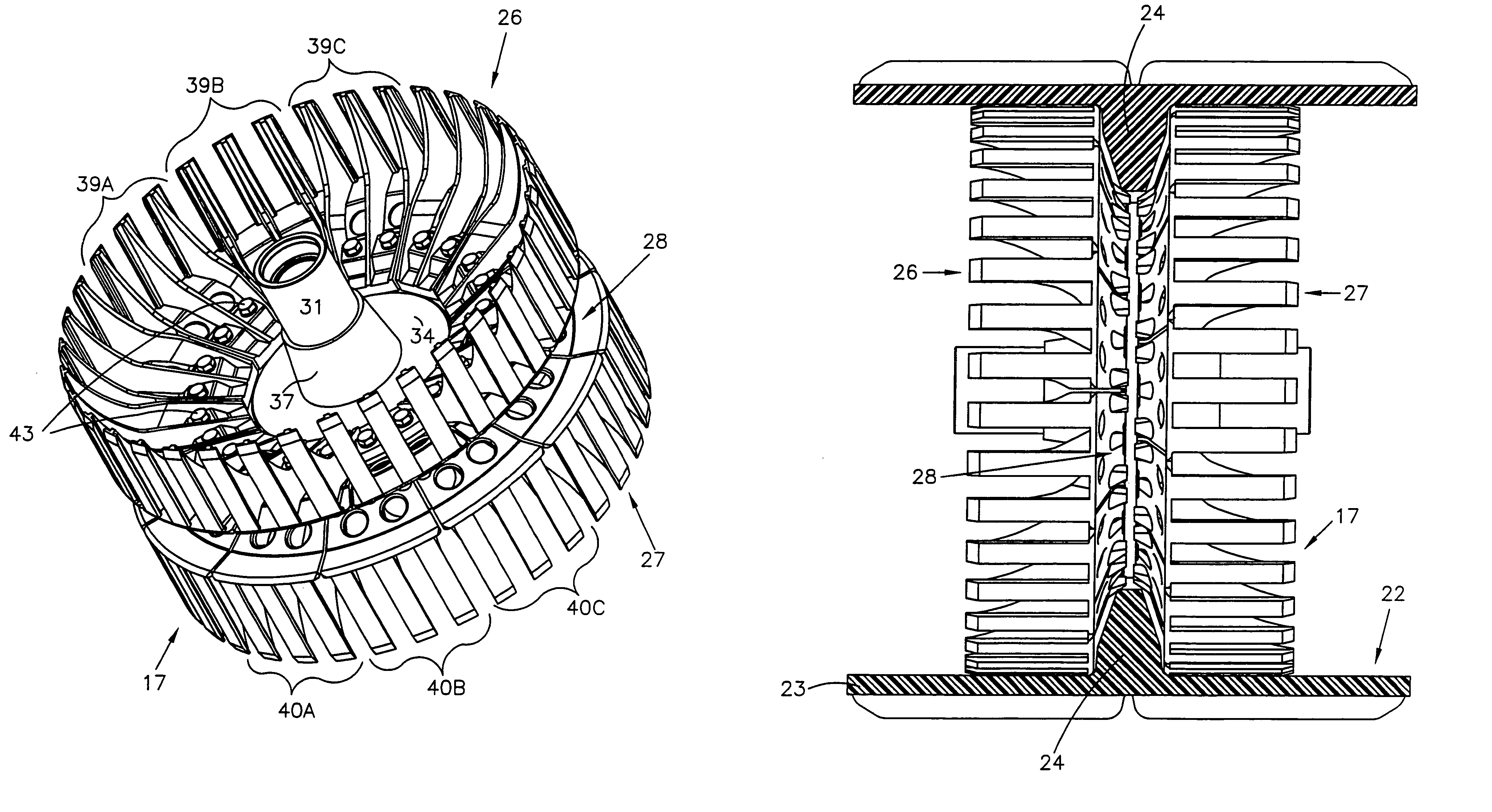
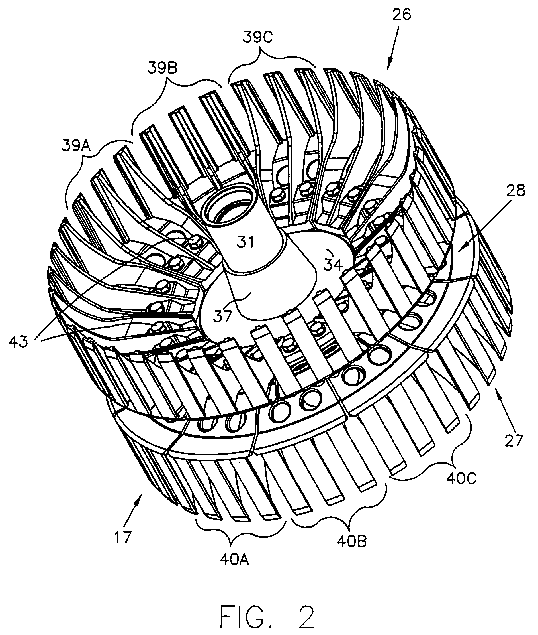
The present invention is about a new type of metal wheel for a belted track vehicle. This wheel is made up of a central hub and a series of individually cast segments. The segments are attached to the hub with bolts and have a "L" shape with feet that engage the track. The wheel is easier to assemble and replace than solid metal wheels and is more accurate in its positioning. It also allows for easier installation and replacement of individual segments. The technical effects of this invention include improved performance, reduced manufacturing costs, and improved ease of maintenance and replacement.

Problems solved by technology

This type of drive wheel is expensive to manufacture since it requires machining of the entire belt engaging surfaces of the belt support elements, as well as machining the regions about the mounting bolts.
Any slight misalignment or unequal tire pressures will cause increased wear because of the friction and rubbing that is generated when the two rubber surfaces are in contact.
However, in the past, metal end wheels have been expensive to manufacture, especially the type of drive wheel disclosed in the above '512 patent wherein the entire wheel is cast integrally, and the traction elements are cantilevered.
Depending on the belt tension system of the vehicle, it may be difficult to replace metal wheels, as explained further below.
Further, it is comparatively expensive to manufacture such integrally cast wheels and to handle and store them.

Method used


Image

  • Wheel for belted track vehicles
  • Wheel for belted track vehicles
  • Wheel for belted track vehicles

Examples


Embodiment Construction

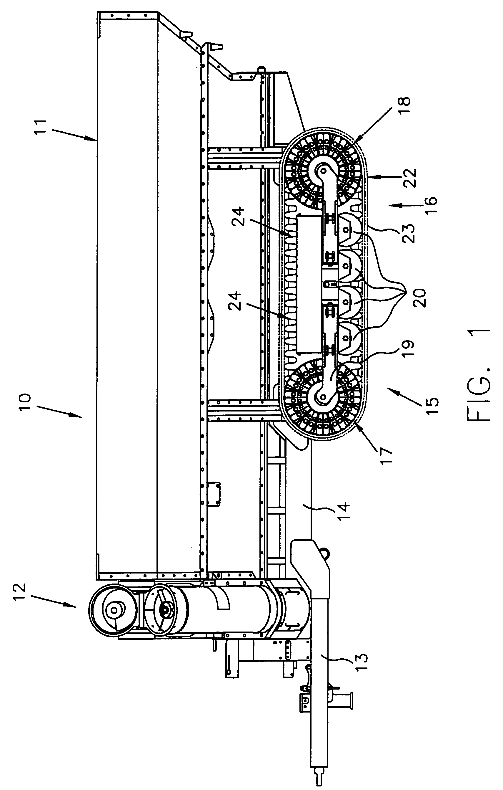
[0034]Referring first to FIG. 1, reference numeral 10 generally designates a vehicle, namely an agricultural grain wagon including a large storage hopper 11, front discharge augers 12, a hitch assembly 13 mounted to a frame 14 and a tracked undercarriage generally designated 15 for supporting the wagon and its contents while permitting the wagon to be pulled by a traction vehicle connected to the hitch assembly 13.

[0035]The vehicle of FIG. 1 includes two separate endless belted track assemblies on the undercarriage 15, the left side belted track assembly being shown in FIG. 1 and designated 16. The right side belted track may be similar to the track assembly 16, and therefore need not be discussed in further detail for a complete understanding of the invention.

[0036]Each belted track assembly 16 includes a forward end wheel 17 and a rear end wheel 18 mounted to the frame 19 of the undercarriage. Four sets of lower idler wheels 20 are conventionally mounted to the carriage frame 19. ...


PUM


Abstract

A wheel for belted track vehicles includes a hub with an upright central disc. A series of individually cast and machined segments are mounted to the disc in side-by-side relation about the periphery of both sides of the disc. Each segment takes the shape of a truncated sector having a general “L” shape as viewed from an end, with a back or base engaging a side of the disc, and belt support elements extending laterally of the disc for engaging and supporting the track.

Description

RELATED APPLICATION[0001]This application claims priority benefit of U.S. provisional application No. 60 / 441,994, filed Jan. 23, 2003.FIELD OF THE INVENTION[0002]The present invention relates to wheels for belted track vehicles, such as a wagon or tractor; and more particularly to a metal wheel which may be fabricated from a hub assembly and a series of individually cast and machined segments mounted side-by-side to the hub assembly and extending circumferentially about the hub to form a wheel.BACKGROUND OF THE INVENTION[0003]Belted track vehicles, including tractors, crawlers and wagons, have found application in the agricultural and construction industries because, among other advantages, they permit operators of agricultural machines to work the field in wetter conditions than are normally permitted with conventional rubber-tire tractors and wagons. Further, belted track vehicles have gained popularity because of their versatility in application. For example, they permit the mach...

Claims


Application Information

Patent Timeline
Patent Type & Authority Patents(United States)
IPC IPC(8): B62D55/12F16H55/30B60B19/00B62D55/135
CPCB60B3/041B60B25/008B62D55/135B60B2310/228B60B2310/302B60B2310/305B60B2360/10B60B2360/147B60Y2200/22
Inventor DECKLER, HARRY C.VOKOUN, RICHARD J.
Owner KINZE MFG INC
Learn More