
Structure of pillar garnish for automobile

a technology for automobiles and pillars, applied in the direction of superstructure connections, belt control systems, transportation and packaging, etc., can solve the problems of considerable sink marks and and achieve the effect of preventing the degradation of the appearance of the pillar garnish

Active Publication Date: 2007-04-03
HONDA MOTOR CO LTD
View PDF2 Cites 2 Cited by
  • Summary
  • Abstract
  • Description
  • Claims
  • Application Information

AI Technical Summary

Benefits of technology

The present invention relates to a pillar garnish structure for automobiles that prevents the degradation of its appearance due to the provision of a webbing guide. The invention provides a structure where a webbing guide is provided on the back of a pillar garnish section covering a pillar, and a plurality of guide beads are provided on the webbing guide at predetermined intervals in a curved manner in the lengthwise direction of the webbing. The guide beads are set at a value larger than the weaving pitch of the webbing, and the back of the pillar garnish is superposed on the surface of the step formed at the end of the other pillar garnish, thereby preventing the degradation of the appearance due to the creation of a sink mark. Reinforcing ribs can be added to increase the rigidity of the leg and stabilize the guiding function of the webbing guide. The height of the guide beads is set at a value equal to or smaller than the thickness of the webbing to prevent an increase in sliding resistance. The invention is particularly useful for a B-pillar in an embodiment.

Problems solved by technology

Therefore, the conventional structure suffers from a problem that a sink mark is created on the surface of the pillar garnish corresponding to the position of the webbing guide, resulting in the degradation of the appearance of the pillar garnish.
Particularly, because the webbing guide is provided directly on the back of the pillar garnish, there is a disadvantage that the height of the webbing guide is increased to cause a considerable creation of sink marks.

Method used


Image

  • Structure of pillar garnish for automobile
  • Structure of pillar garnish for automobile
  • Structure of pillar garnish for automobile

Examples


Embodiment Construction

[0022]The present invention will now be described by way of an embodiment shown in the accompanying drawings.

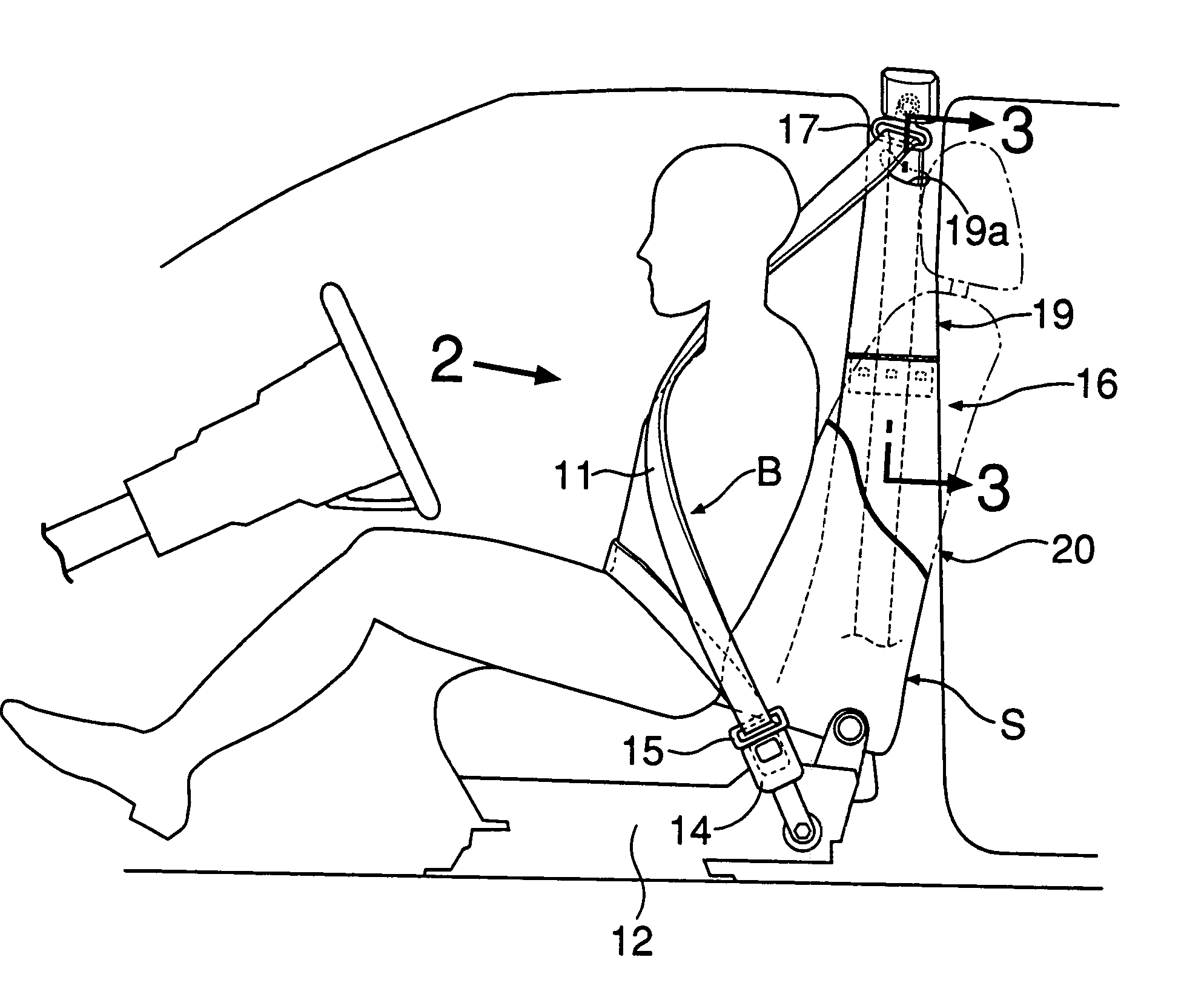
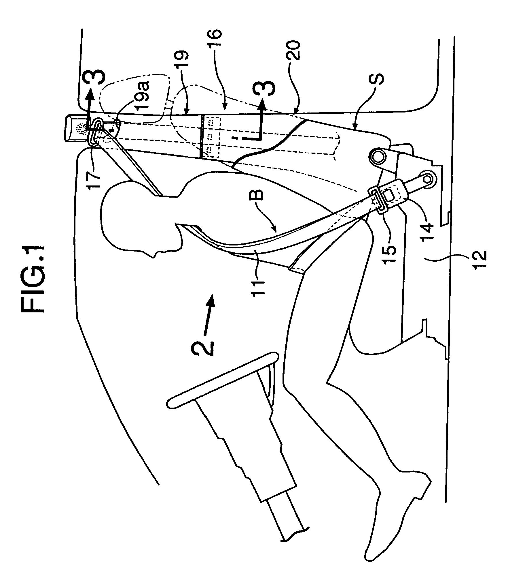
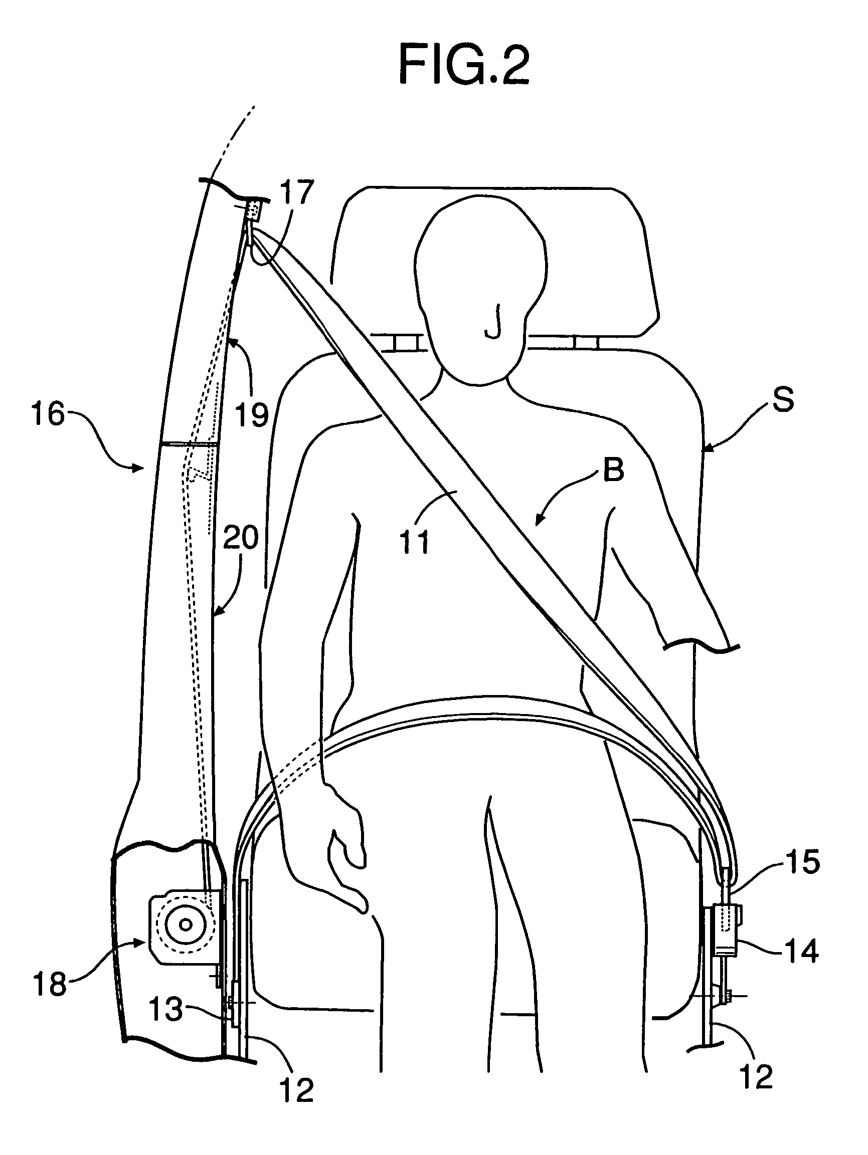
[0023]Referring to FIGS. 1 and 2, a webbing 11 of a seat belt device B for restraining an occupant on a seat S in a front row, extends from one end fixed to an anchor 13 mounted on a right side of a seat base 12, through a tongue 15 detachably coupled to a buckle 14 mounted on a left side of the seat base 12, a through-anchor 17 mounted at an upper portion of a B-pillar 16 (a center pillar) and an inside of the B-pillar 16, so that the other end of the webbing 11 is wound up around a retractor 18. A side of the B-pillar on the side of a vehicle compartment is covered with an upper pillar garnish 19 made of a synthetic resin and a lower pillar garnish 20 made of a synthetic resin. The webbing 11 is guided through an opening 19a (see FIG. 3) formed in the upper pillar garnish 19 into the inside of the B-pillar 16.

[0024]As can be seen from FIGS. 3 to 5, a step 19b is formed at a...


PUM


Abstract

In a structure of a pillar garnish for an automobile, a leg is provided to protrude toward a webbing from a lower edge of a step formed at a lower end of one of an upper pillar garnish and a lower pillar garnish which are formed by dividing a pillar garnish section, and webbing guide is provided at a tip end of the leg. Therefore, even if a sink mark is created on a surface of the step of the upper pillar garnish corresponding to the position of the leg, the sink mark is covered with an upper end of the lower pillar garnish and thus invisible from the side of a vehicle compartment, so that it is possible to prevent the degradation of the appearance due to the creation of the sink mark. Moreover, a back of the lower pillar garnish is superposed on a surface of the step formed on the upper pillar garnish. Therefore, it is possible to prevent the generation of a difference in level at a joint between both of the pillar garnishes to enhance the appearance.

Description

RELATED APPLICATION DATA[0001]The Japanese priority application No. 2004-62002 upon which the present application is based is hereby incorporated in its entirety herein by reference.BACKGROUND OF THE INVENTION[0002]1. Field of the Invention[0003]The present invention relates to a structure of a pillar garnish for an automobile in which a webbing guide for slidably guiding a webbing of a seat belt device is provided on a back of a pillar garnish section covering a pillar.[0004]2. Description of the Related Art[0005]A webbing of a seat belt device for an automobile is drawn from the inside of a vehicle compartment to a back of a pillar garnish and wound around a retractor. Japanese Utility Model Application Laid-open No. 61-78064 discloses a structure of a pillar garnish for an automobile, in which a webbing guide for slidably guiding a webbing is provided on a back of a pillar garnish, in order to prevent smooth sliding of the webbing from being obstructed by the webbing being rubbed...

Claims


Application Information

Patent Timeline
Patent Type & Authority Patents(United States)
IPC IPC(8): B60R22/00B60R22/24B60R13/02B60R22/18
CPCB60R13/025B60R22/24B60R22/26B60R2022/1818
Inventor KAJIWARA, HIDEKISUGIMOTO, JUNJIKASAI, TAKAMITSUSEKIGUCHI, NOBUMOTO
Owner HONDA MOTOR CO LTD
Learn More