
Variable test object and holder for variable test objects

a test object and variable technology, applied in the field of variable test objects, can solve the problems of inflexibility, inability to adapt the distance of balls to the relevant measurement requirements, and defined and constant distances of balls, so as to facilitate the use facilitate stable position and flexible use of test objects, and facilitate the effect of variable target distances

Inactive Publication Date: 2007-04-03
METRONOM
View PDF10 Cites 11 Cited by
  • Summary
  • Abstract
  • Description
  • Claims
  • Application Information

AI Technical Summary

Benefits of technology

[0022]A test object according to the invention is characterised in that it is suitable for use in the holder according to the invention and facilitates variable target distances, whereby the holder according to the invention can be adapted to the relevant test object and at the same time facilitates a stable position and flexible usage of the test object.
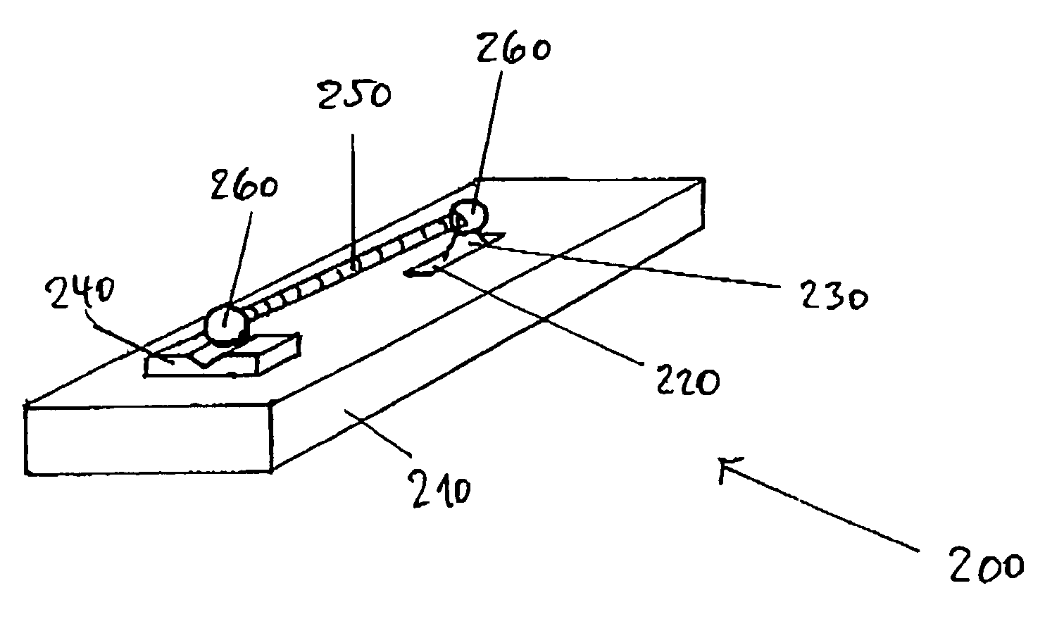
[0040]Another advantageous further development is characterised in that the combination of the seats exhibits at least one degree of directional freedom, wherein the relevant degree of freedom points in the direction of the connecting line of the connected targets, so that the targets and the connecting elements are not subject to any stresses. This is, for example, facilitated by a combination of point and V-supports. Optionally, a flat seat can also be used. This type of arrangement is characterised in that a stress-free setting up of the test object can occur and that the test object is also held free of stress. If the first target, for example, is placed on a point seat and then the connecting element is coupled magnetically to the first target, then finally the second target can be brought on a V-seat and, free of force, coupled onto the other end of the connecting element. In this way it is furthermore possible to add further connecting elements and targets to build them up on the holder to form a larger test object, such as for example a ball bar. Stress-free branches on a ball bar can then be achieved with flat seats.

Problems solved by technology

Although measurements with interferometers supply reliable information on the precision of the inspected machines, such a method in practice is very time consuming, so that the monitoring intervals are often chosen to be very long, e.g. annual.
The test objects known from the state of the art have either the disadvantage of being inflexible due to the given ball distances or of being unusable due to a holder that is unsuitable for many purposes.
With the holder with fixed ball mountings it is disadvantageous that the distances of the balls are defined and constant due to the fixed position of the ball holders on the carrier body.
Adaptation of the ball distances to the relevant measurement requirements is therefore not possible.
If the balls and bars are clamped, then stresses arise which can impair the measurement result, which is a disadvantage.
Furthermore, a poorer temperature neutrality when using steel as the material for the distance tubes is also disadvantageous.
If a ball bar is placed on single seats, then adequate linear alignment of the ball bar must be ensured in order to achieve a low alignment error, which can only be obtained conditionally and with difficulty using seats which have to be adjusted independently of one another and which therefore is disadvantageous.
In the case of ball bars with variable lengths of the connecting elements, such a construction is either unstable and therefore is not easily used or difficult to align and can only be positioned as required in the measurement volume with a great deal of adjustment.

Method used


Image

  • Variable test object and holder for variable test objects
  • Variable test object and holder for variable test objects
  • Variable test object and holder for variable test objects

Examples


Embodiment Construction

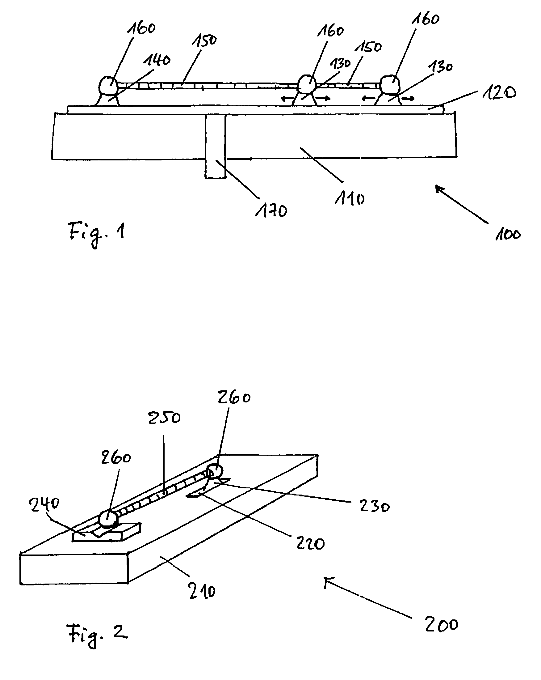
[0048]FIG. 1 shows a test object according to the invention on a holder according to the invention. In this example the test object is a ball bar with two connecting elements 150 and three targets 160, which are held together releasably by magnetic forces. Here, the connecting elements and targets are selected from a given set in which at least two connecting elements of different length are provided, so that different target distances can be realised. The holder comprises a carrier 110, which can be disassembled into single elements which are held together by a releasable connection 170, as well as a guide 120 for the seats 130, 140 on which the targets are located. One seat 140 is fixedly fitted to the carrier so that the exact position of the target located on it is also known relative to the holder. Two seats 130 are movable, so that adaptation of the position of the seats to the lengths of the connecting elements and the distances and positions of the targets they define is pos...


PUM


Abstract

The invention relates to a holder for test objects, which are composed of at least two targets and at least one connecting element, comprising at least one carrier, at least one guide, which is arranged on or / and in the at least one carrier, and seats for the targets of at least one test object, wherein at least one seat can be moved along the at least one guide such that an adaptation of the position of the at least one movable seat to the position of one target of the test object is possible. Furthermore, the invention relates to a test object for the holder previously mentioned, comprising at least two targets and at least one connecting element, wherein the targets and connecting elements can be selected from a given set of single targets and single connecting elements and combined to form a test object.

Description

FIELD OF THE INVENTION[0001]The invention relates to a variable test object, which consists of at least two targets and a connecting element, and a holder for such variable test objects.BACKGROUND OF THE INVENTION[0002]For the monitoring of co-ordinate measurement machines and production devices, measurements on test objects are required which acquire the main deviations of the measurement machine or the production device. As mechanical comparative standards, such test objects represent an economical alternative to measuring comparative standards, such as for example interferometers. Although measurements with interferometers supply reliable information on the precision of the inspected machines, such a method in practice is very time consuming, so that the monitoring intervals are often chosen to be very long, e.g. annual. Modern machine tools and industrial robots operate in tight tolerance ranges and sometimes exhibit drift characteristics so that more frequent checking is necess...

Claims


Application Information

Patent Timeline
Patent Type & Authority Patents(United States)
IPC IPC(8): G01B3/00G01D21/00G01B21/04
CPCG01B21/042
Inventor HEIMER, DIETMAR
Owner METRONOM
Learn More