Eureka AIR delivers breakthrough ideas for toughest innovation challenges, trusted by R&D personnel around the world.

Optical disk medium and optical disk recording and reproducing apparatus

a technology of optical disk and recording medium, which is applied in the direction of digital signal error detection/correction, instruments, recording signal processing, etc., can solve the problems of reducing the reliability of correcting errors, and increasing the time required to seek address information in random access. good high-density recording

Inactive Publication Date: 2007-03-27
KK TOSHIBA +1
View PDF10 Cites 5 Cited by
  • Summary
  • Abstract
  • Description
  • Claims
  • Application Information

AI Technical Summary

Benefits of technology

[0020](A) An object of the present invention is to provide an optical disk medium, an optical disk recording and reproducing apparatus, an optical disk recording and reproducing method which are capable of making good high-density recordings without causing the aforementioned problems.
[0021](B) Another object of the present invention is to provide an optical disk medium, an optical disk recording and reproducing apparatus, an optical disk recording and reproducing method which are capable of detecting format information stably by using a wobble method as a method of recording format information on a land-groove optical disk.

Problems solved by technology

When a physical segment is too long, the time required to seek address information in random access increases.
In this method, however, the prepit part cannot be used as a data area.
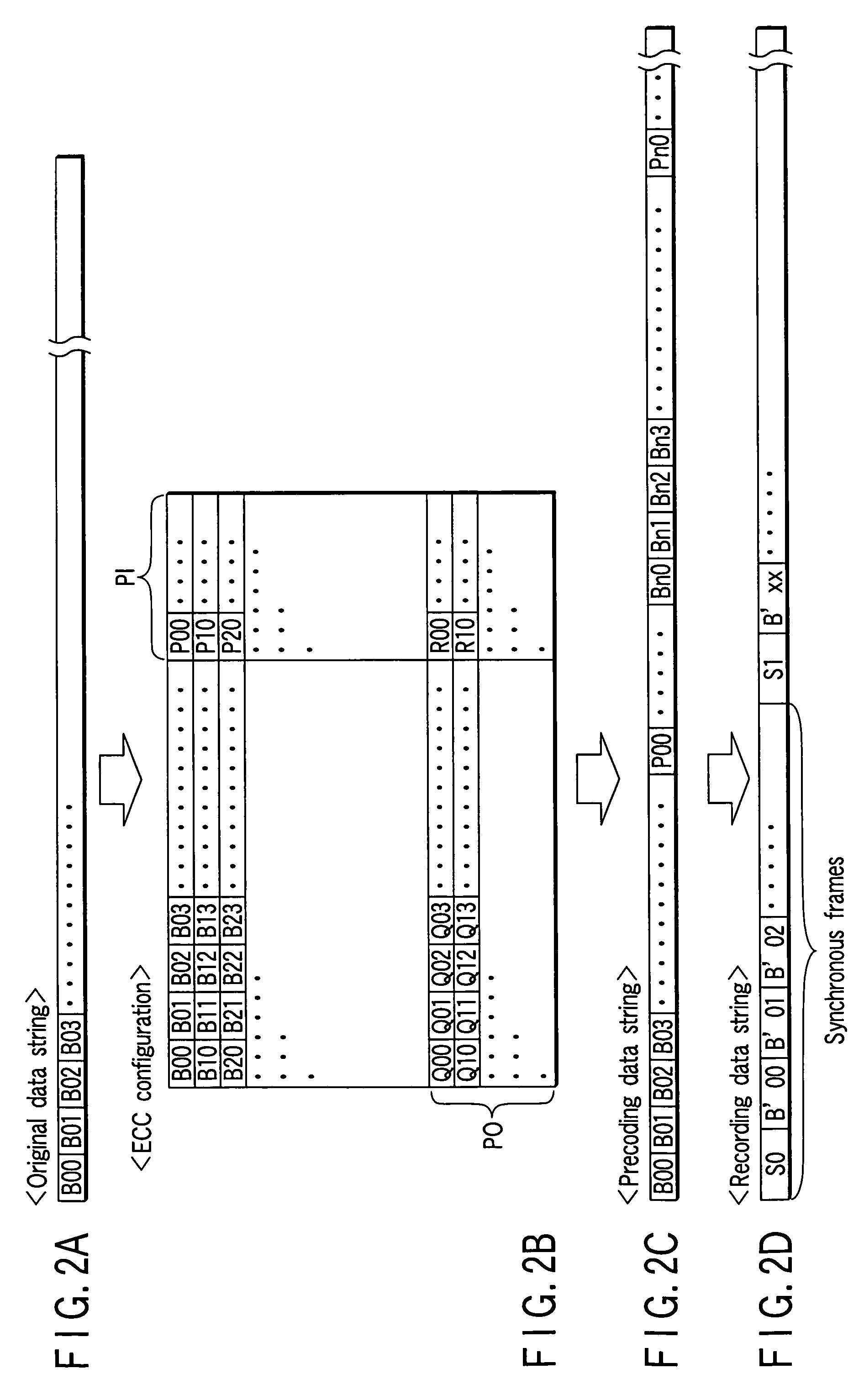
The problems here are that highly correlative data items are arranged at regular intervals in the recording data string and that format modulation sections (for example, address information) are present at regular intervals also in a physical segment.
However, when errors concentrate in a specific column or row, the reliability of correcting errors decreases as compared with the case where errors take place at random.
However, in the case of next-generation optical disks with much higher recording density, the present configuration has the problem that the format information has too significant an effect on the deterioration of the recording / reproducing data.
Furthermore, in recent years, optical disks have been required to have much larger capacity.
In the case of the land-groove optical disk, however, the problem is how to configure format information (addresses) for the land recording track and format information (addresses) for the groove recording track.

Method used


Image

  • Optical disk medium and optical disk recording and reproducing apparatus
  • Optical disk medium and optical disk recording and reproducing apparatus
  • Optical disk medium and optical disk recording and reproducing apparatus

Examples


Embodiment Construction

[0065]Hereinafter, by referring to the accompanying drawings, embodiments of the present invention will be explained.

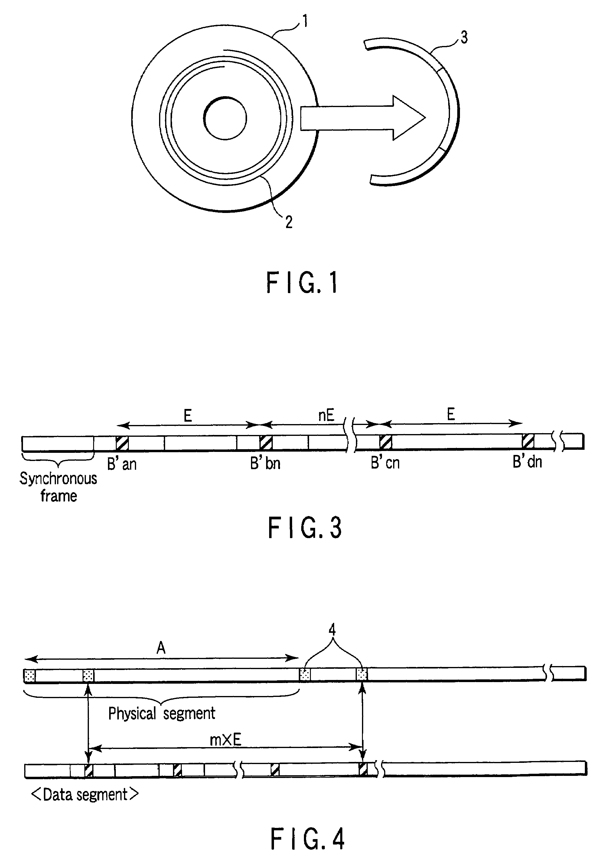
[0066]Before explanation of a concrete example of the present invention, underlying techniques will be described. In FIG. 1, an optical disk 1 generally has a recording track 2 formed spirally. The recording track 2 is divided into physical segments of a specific length. An address is allocated to each of the physical segments 3. The address is written into each segment as preformat data.

[0067]In an optical disk using the CLV system in which the recoding line density is constant, all of the physical segment lengths are equal. Since too long physical segment lengths lead to an increase in the time required to search for address information in random access, such a length as contains ten to several tens of physical segments 3 in one circumference is selected.

[0068]One preformatting method is to form a prepit at the head of a physical segment 3. The preformat part cannot...


PUM

PropertyMeasurementUnit
reflectivityaaaaaaaaaa
lengthaaaaaaaaaa
frequencyaaaaaaaaaa

Abstract

A recording data string is composed of a plurality of synchronous frames each of which has synchronous data and coding data. Data items in the coding data contributed to creation of the same column of the error correction code are arranged at regular intervals of E in the recording data string. A data segment length L is obtained by adding an additional synchronous frame to the recording data string. Wherein, a physical segment length A satisfies the equation L=mA, m is a natural number. And A is set indivisible by E.

Description

CROSS-REFERENCE TO RELATED APPLICATIONS[0001]This application is based upon and claims the benefit of priority from the prior Japanese Patent Application No. 2003-040444,filed Feb. 19, 2003, the entire contents of which are incorporated herein by reference.BACKGROUND OF THE INVENTION[0002]1. Field of the Invention[0003]This invention relates to an optical disk medium and an optical disk recording and reproducing apparatus which are capable of recording and reproducing information with a very small light spot.[0004]2. Description of the Related Art[0005]In a recording optical disk, preformat information has been recorded on the optical disk. When data is recorded-onto the optical disk with an optical disk unit, the preformat information is detected and the recording position for the data is determined by reference to the detected information.[0006]Usually, the recording track formed in spiral fashion on the optical disk is divided into physical segments of a specific length. Addresse...

Claims


Application Information

Patent Timeline
Patent Type & Authority Patents(United States)
IPC IPC(8): G11B7/24G11B20/10G11B7/004G11B7/007G11B20/12G11B20/14G11B20/18
CPCG11B20/1217G11B20/1833G11B2020/1222G11B2220/2562G11B2020/1239G11B2020/1265G11B2020/1278G11B2020/1232
Inventor NODA, CHOSAKUSATO, HIROHARUOHSAWA, HIDEAKIYAMANAKA, YUTAKAKAYANUMA, KINJIIWANAGA, TOSHIAKI
Owner KK TOSHIBA
Why Eureka
Eureka Blog
Learn More