
Fiber-optic sensing system

a fiber optic and sensing technology, applied in the field of sensing physical parameters, can solve the problem that the sensor cannot monitor the pressure of soft tissue, and achieve the effect of low cos

Inactive Publication Date: 2007-03-27
YIP KIN MAN +1
View PDF19 Cites 23 Cited by
  • Summary
  • Abstract
  • Description
  • Claims
  • Application Information

AI Technical Summary

Benefits of technology

"The present invention provides a low-cost and simple fiber-optic sensing system for measuring pressure or temperature, with minimal invasiveness and adaptable for in-vivo measurement. The system includes an outer sheath with windows, an optical fiber running from the sheath to a data processing and read-out instrument, and a designated number of in-fiber sensing elements along the length of the optical fiber. The sensing elements can be fiber Bragg grating, long period grating, or periodic surface corrugation that exhibits long period grating effect under deformation. The system can also include a flexible diaphragm downstream of the windows for measuring fluid pressure when the sheath is put into a fluid environment. The overall size of the sensor is greatly reduced, and the system can be directly inserted into the body without using an additional catheter, resulting in minimal invasiveness and discomfort. The fiber gratings as sensors are coded in the wavelength and so intensity fluctuation of the source or random losses caused by bending will not affect the accuracy of measurement, and temperature-induced drift in the measurement can be compensated by an independent grating in the same fiber that is exposed to the same temperature but not to the pressure."

Problems solved by technology

This sensor will not be able to monitor pressure from soft tissue or fluid that is too viscous to pass into the interior of the sheath through the windows.

Method used


Image

  • Fiber-optic sensing system
  • Fiber-optic sensing system
  • Fiber-optic sensing system

Examples


Embodiment Construction

[0034]A description will now be given of the preferred embodiments of the present invention with reference to the drawings.

[0035]In the drawings, the same numeral notation refers to the same element. The drawings and the following detailed descriptions show specific embodiments of the invention. In the preferred embodiment, polymeric adhesive was employed to manufacture the flexible diaphragm and spinal needle was employed as the sheath. Numerous specific details including materials, dimensions, and products are provided to illustrate the invention and to provide a more thorough understanding of the invention. However, it will be obvious to one skilled in the art that the present invention may be practiced using other materials for the sheath and flexible diaphragm and without these specific details.

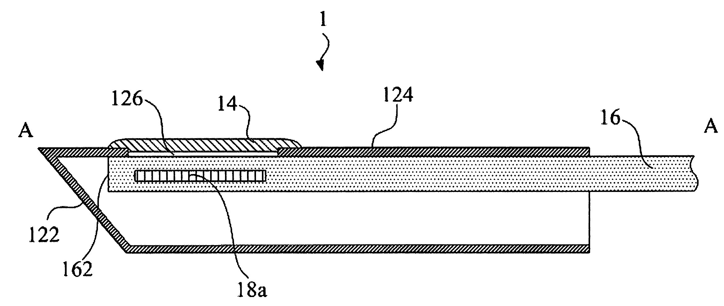
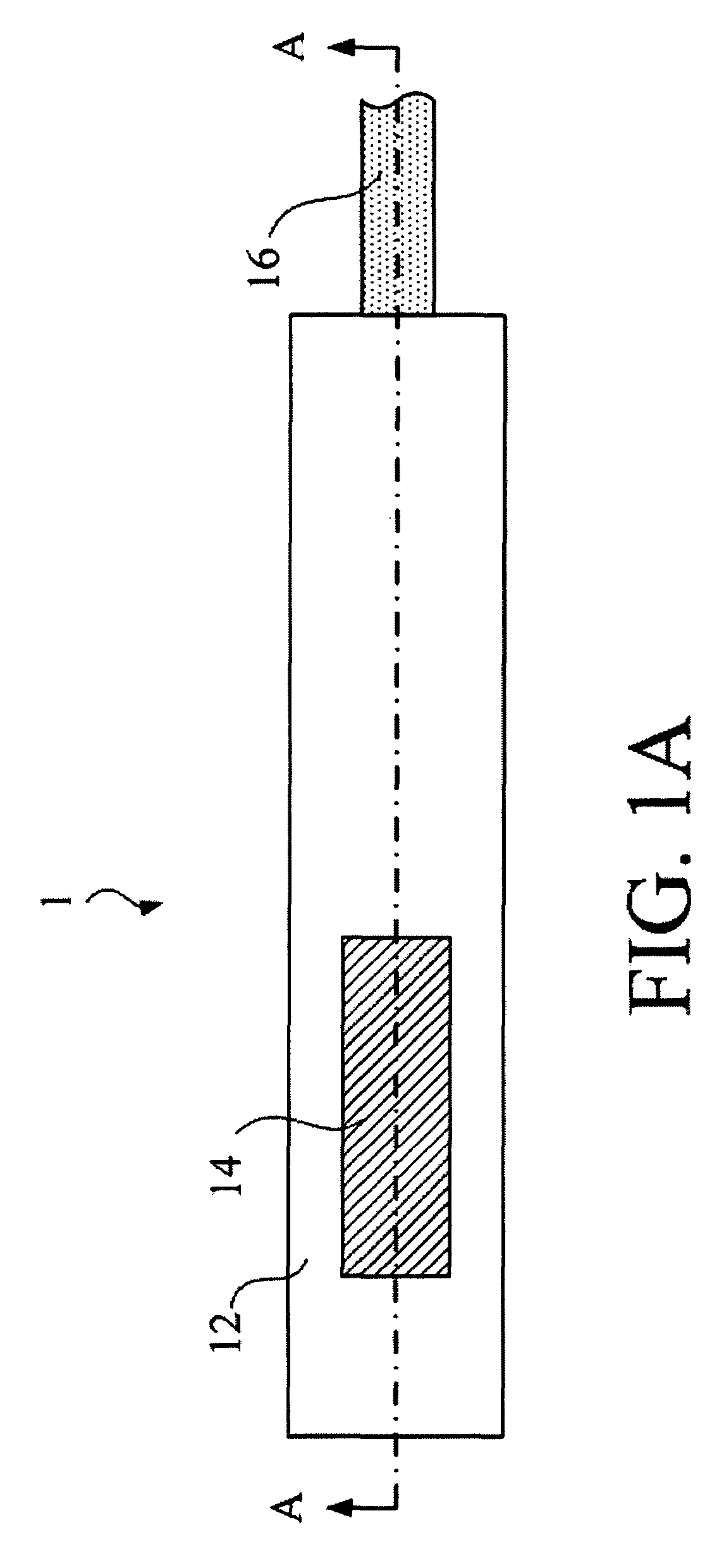
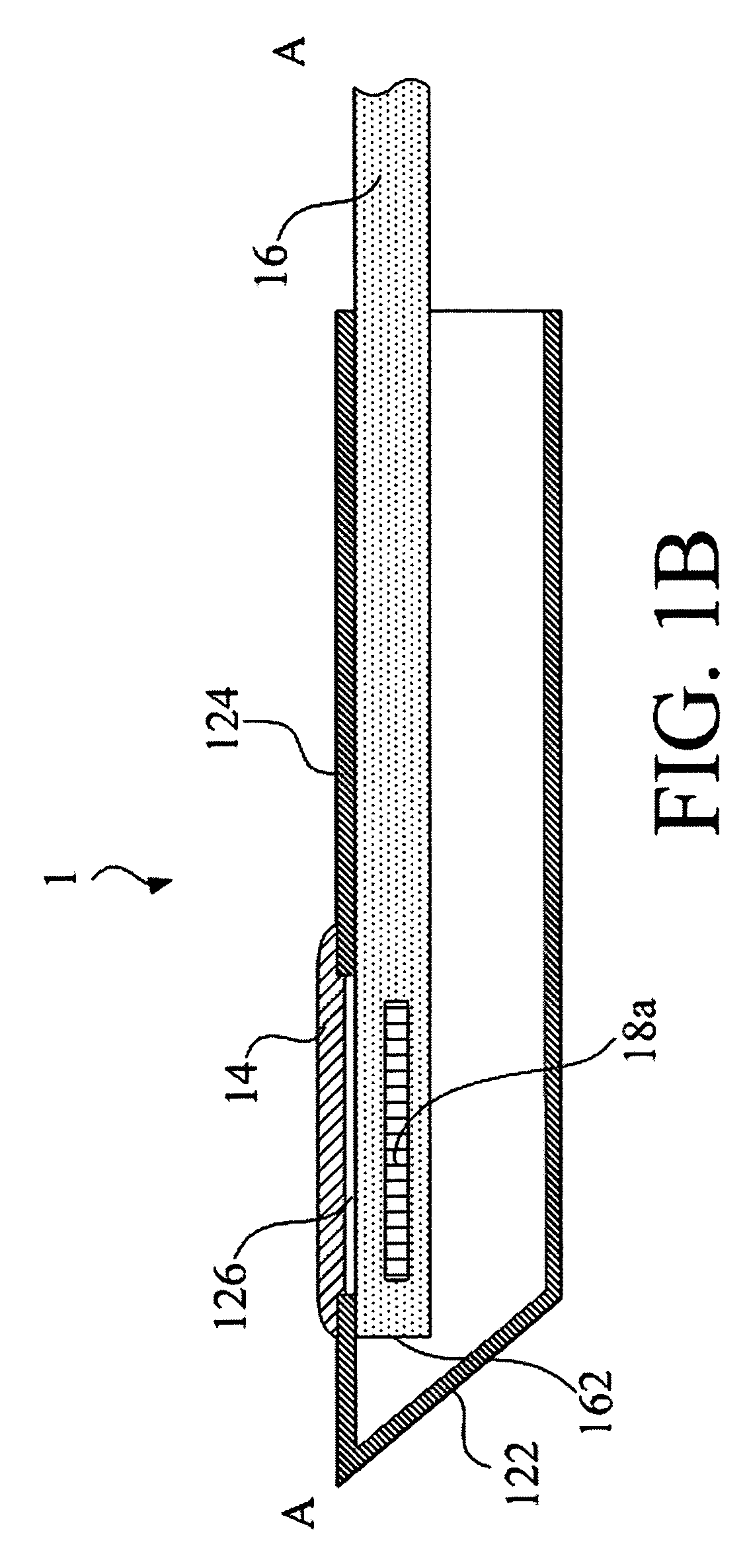
[0036]FIG. 1A is an outside perspective view of a needle 12 and an optical fiber 16, disposed in the needle 12, of a fiber-optic sensing system 1 according to a preferred embodiment of t...


PUM


Abstract

The invention provides a fiber-optic sensing system, utilizing a fiber-grating-based sensor, for a physical parameter, e.g., a pressure or a temperature. Different kinds of fiber-grating-based sensors may be used for this purpose but in-fiber gratings such as Fiber Bragg Grating, Long Period Grating and Surface Corrugated Long Period Fiber Grating are particularly suitable. Due to the small size of the optical fiber and the fact that same fiber acts as the sensing element as well as the signal conducting medium, it is possible to install the sensor in a small diameter needle which is commonly used for medical diagnosis and treatment. As a result, when the fiber-optic sensing system of the invention is used for in-vivo measurement of a biological parameter, such a sensing needle can be used for different in-vivo pressure or temperature sensing applications without causing too much harm and discomfort to the subject tested.

Description

BACKGROUND OF THE INVENTION[0001]1. Field of the Invention[0002]This invention relates to the sensing of physical parameter, such as pressure or temperature, using in-fiber sensors, e.g., short period fiber Bragg grating, long period fiber grating or surface corrugated long period fiber grating. Since signal sensing and signal transfer can both occur in the same fiber, it is possible to derive miniature pressure or temperature sensing systems or transducers for use in medical diagnoses in the areas of intradiscal, intracranial, intramuscular, intra-articular, ventricular pressure or temperature monitoring with minimum invasiveness. For example, for intra-articular pressure measurement, the small size of the needle means that the pressure of small joint cavities like the temporo-mandibular joint, the facet joints of the vertebral column, the carpal joints of the wrist and the tarsal joints of the midfoot region can also be assessed by means of this device. With respect to the technol...

Claims


Application Information

Patent Timeline
Patent Type & Authority Patents(United States)
IPC IPC(8): G01J5/08
CPCA61B5/01A61B5/03G01K11/3206A61B5/6848G01D5/35303A61B5/4514G01D5/35316G01D5/35354
Inventor SHIN, CHOW-SHINGYIP, KIN-MANCHIANG, CHIA-CHIN
Owner YIP KIN MAN
Learn More