Compact electrical wiring system

a technology of electrical wiring and compact structure, applied in the direction of coupling device connection, coupling protective earth/shielding arrangement, tumbler/rocker switch, etc., can solve the problems of electromagnetic noise, adversely affecting the performance of electronic equipment such as computers, telecommunications equipment, testing and calibration equipment, etc., to prevent the propagation of electromagnetic noise, save labor and cost, and save energy

Inactive Publication Date: 2007-03-27
PASS SEYMOUR
View PDF4 Cites 42 Cited by
  • Summary
  • Abstract
  • Description
  • Claims
  • Application Information

AI Technical Summary

Benefits of technology

[0011]The present invention addresses the needs identified above. The present invention provides an efficient, labor saving, and cost-effective system for terminating electrical devices to the electric

Problems solved by technology

Electrical circuit installation is a labor intensive and time consuming process that may require electricians of various skill levels.
There are drawbacks to the process described above.
One drawback relates to the rough-in phase of the process, while another drawback relates to the termination phase.
While this grounding method affords protection to both personnel and equipment, it may be problematic from an electromagnetic (EMI) standpoint.

Method used


Image

  • Compact electrical wiring system
  • Compact electrical wiring system
  • Compact electrical wiring system

Examples


Embodiment Construction

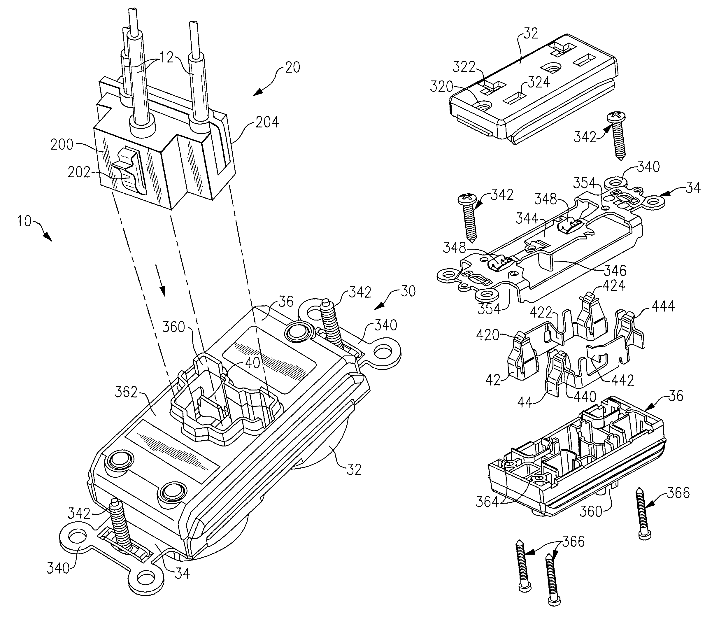
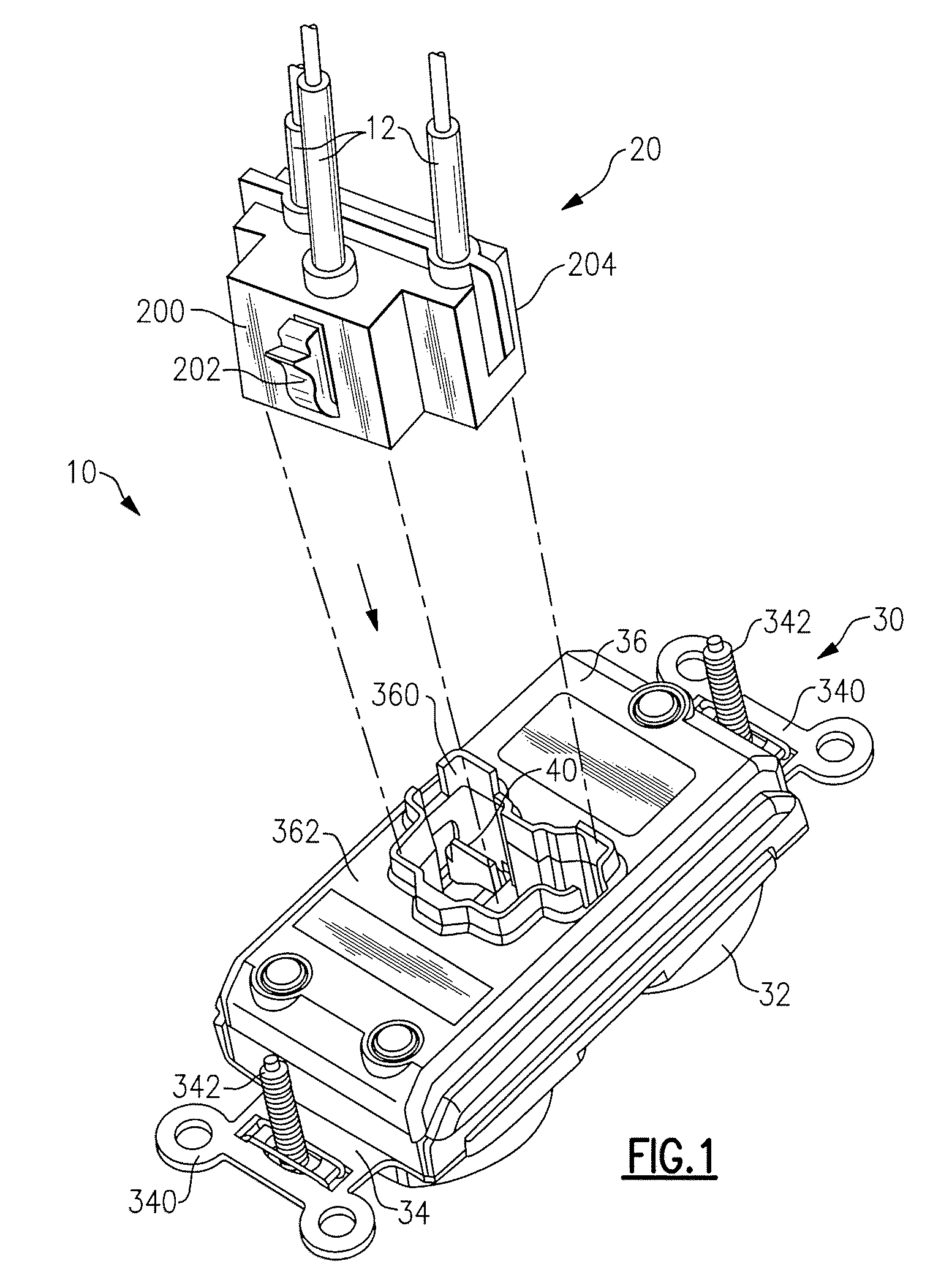
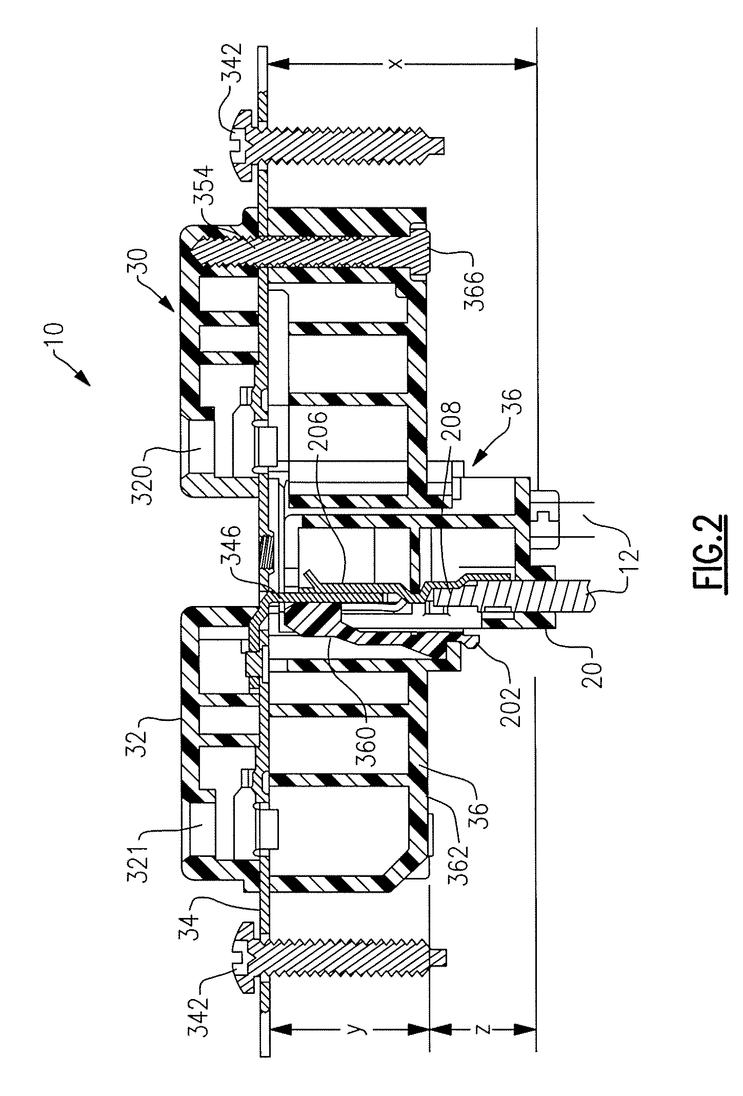
[0026]Reference will now be made in detail to the present exemplary embodiments of the invention, examples of which are illustrated in the accompanying drawings. Wherever possible, the same reference numbers will be used throughout the drawings to refer to the same or like parts. An exemplary embodiment of the electrical wiring system of the present invention is shown in FIG. 1, and is designated generally throughout by reference numeral 10.

[0027]In accordance with the invention, the present invention is directed to an electrical wiring system that includes a plug connector including a plurality of plug contacts. The plug connector is configured to terminate a plurality of wires. An electrical wiring device includes a cover member, a body member, and a ground strap disposed between the cover member and the body member. The body member includes a receptacle configured to accept the plug connector and a plurality of device contacts. The plurality of device contacts are configured to m...


PUM


Abstract

The present invention is directed to a electrical wiring system that includes a plug connector having a plurality of plug contacts configured to terminate a plurality of wires. The system also includes an electrical wiring device having a cover member, a body member, a ground strap assembly disposed between the cover member and the body member, and a receptacle formed in a rear portion of the body member, the receptacle being configured to accept the plug connector. The ground strap assembly is configured to conform to at least one body member feature such that a distance from the ground strap assembly to a major rear surface of the body member is less than a predetermined distance. The receptacle includes a plurality of receptacle contacts configured to mate with the plurality of plug contacts when the plug connector is inserted into the receptacle.

Description

CROSS-REFERENCE TO RELATED APPLICATIONS[0001]This is a continuation of U.S. patent application Ser. No. 11 / 032,420 filed on Jan. 10, 2005, which is a continuation-in-part of U.S. patent application Ser. No. 10 / 680,797 filed on Oct. 7, 2003, now U.S. Pat. No. 6,994,585, the contents of which is replied upon and incorporated herein by reference in their entirety, and the benefit of priority under 35 U.S.C. §120 is hereby claimed.BACKGROUND OF THE INVENTION[0002]1. Field of the Invention[0003]The present invention relates generally to electrical devices, and particularly to electrical wiring devices.[0004]2. Technical Background[0005]Electrical circuit installation is a labor intensive and time consuming process that may require electricians of various skill levels. Essentially, the process includes several phases. The first phase is commonly referred to as the rough-in stage. The second stage may be referred to as the termination phase.[0006]During the rough-in stage either conduit or...

Claims


Application Information

Patent Timeline
IPC IPC(8): H01R13/60
CPCH01R23/10H01R13/65802H01R13/6272H01R2103/00H01R13/655H01R24/78
Inventor SAVICKI, JR., GERALD R.
Owner PASS SEYMOUR
Why Eureka
Try Eureka