
Hoof trimming stall

a technology for hoofs and stalls, which is applied in the field of hoof trimming stalls, can solve the problems of not being able to securely immobilize the animal, stalls that are not portable, and currently available commercial stalls that suffer from one or more disadvantages, and achieve the effect of fast animal throughpu

Inactive Publication Date: 2007-03-27
DE VOR ALBERT
View PDF23 Cites 12 Cited by
  • Summary
  • Abstract
  • Description
  • Claims
  • Application Information

AI Technical Summary

Benefits of technology

"The present invention provides a hoof trimming stall that has a frame with a front and rear portion, a front gate, and a door lock / release mechanism. The stall also has a reset mechanism for automatically resetting the doors and a floor lift for supporting the animal while its legs are raised for trimming. The stall is designed to prevent the animal from backing out and to provide a comfortable and safe environment for trimming. The technical effects of the invention include improved safety, convenience, and efficiency in the trimming process."

Problems solved by technology

Although many commercial stalls are available for this purpose, currently available commercial stalls generally suffer from one or more disadvantages.
For example, such stalls may not be portable.
They may not securely immobilize the animal.
Loading animals into such stalls may not be easy and / or quick.
The stalls may not provide easy and / or quick access to the animal's hooves.
Unloading animals from such stalls may not be easy and / or quick.
As a result, precious time is lost during the hoof trimming operation resulting in fewer animals that can have their hooves trimmed in a given period time.

Method used


Image

  • Hoof trimming stall
  • Hoof trimming stall
  • Hoof trimming stall

Examples


Embodiment Construction

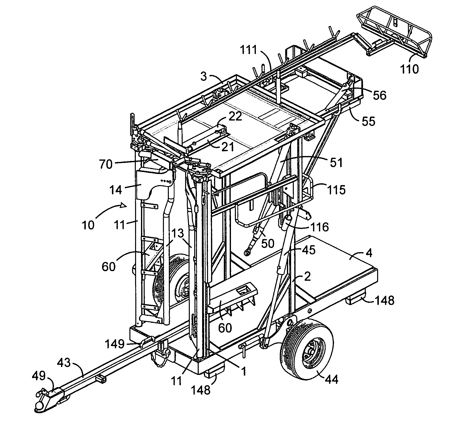
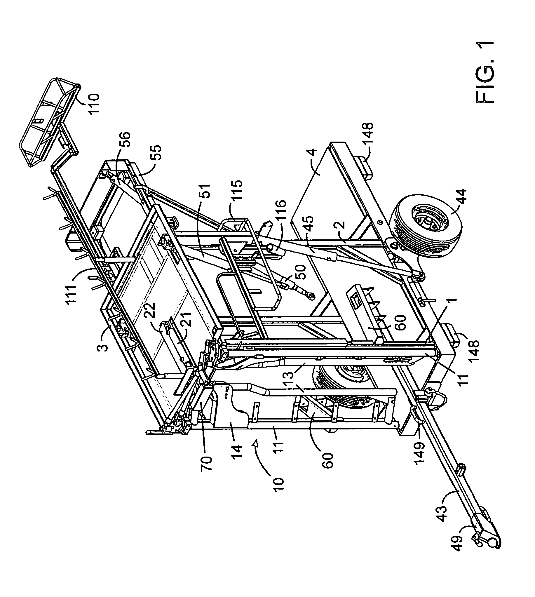
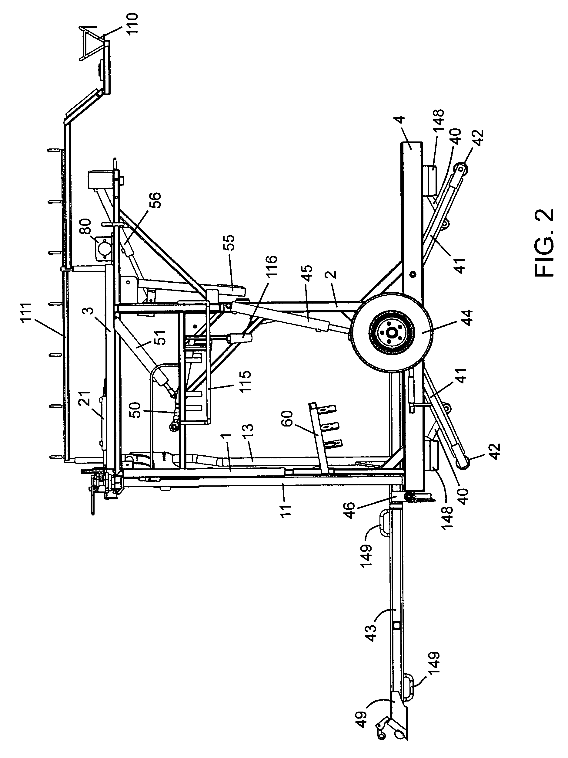
[0031]Referring generally to the Figures, a hoof trimming stall has a frame including front side support struts 1, rear side support struts 2, roof 3 and floor 4. Front gate 10 mounted at the front of the stall has two side-by-side spaced-apart doors 11 shown in a catching position in FIG. 1. Doors 11 are constructed of cylindrical pipes and are pivotally mounted on the frame at fixed points at the top and bottom alongside front side support struts 1 so that the pivot axis is parallel to front side support struts 1. The doors comprise vertical head rails 13 adjustably attached to head plates 14 proximal the top and pivotally attached to the doors at the bottom. The head rails define a gap between the doors, which is large enough in the catching position to accommodate the head of animal but small enough to prevent the entire animal from passing completely between the doors in the catching position. When an animal enters the stall from the rear, the animal's head passes through the g...


PUM


Abstract

A hoof trimming stall has a front gate having two pivotally mounted spaced-apart doors for swinging inwardly and outwardly. The doors are movable between a catching position in which the doors point inwardly for receiving a head of the animal entering the stall, a closed position for holding the animal in the stall with the neck of the animal caught in a gap between the doors, and an open position in which the doors point outwardly for permitting the animal to exit. A door lock / release mechanism has a slider arm movable forward and backward, a hydraulic cylinder for moving the slider arm forward and backward, a rear catcher mounted on the slider arm for preventing the doors from moving from the closed position to the catching position, a front catcher mounted on the slider arm for preventing the doors from being opened by the animal when the doors are in the closed position, and a release mechanism for permitting the doors to move from the open position to the catching position. An automatic reset mechanism automatically resets the doors and door / lock release mechanism. The reset mechanism has a sensor for signaling the hydraulic cylinder to move the slider arm backwards when the doors are in the open position and a spring for biasing the doors from the open position to the catching position.

Description

FIELD OF THE INVENTION[0001]This invention is related to hoof trimming stalls for hoofed animals such as cattle, horses and the like.BACKGROUND OF THE INVENTION[0002]Large hoofed animals in a farm setting frequently require hoof trimming. Due to the size and weight of such animals, in order to trim their hooves safely, the animals are usually immobilized in a stall before hoof trimming is commenced. Although many commercial stalls are available for this purpose, currently available commercial stalls generally suffer from one or more disadvantages. For example, such stalls may not be portable. They may not securely immobilize the animal. Loading animals into such stalls may not be easy and / or quick. The stalls may not provide easy and / or quick access to the animal's hooves. Unloading animals from such stalls may not be easy and / or quick. As a result, precious time is lost during the hoof trimming operation resulting in fewer animals that can have their hooves trimmed in a given perio...

Claims


Application Information

Patent Timeline
Patent Type & Authority Patents(United States)
IPC IPC(8): A01L11/00A01K1/00A01K15/04
CPCA01K1/0613A01L15/00A01L13/00A01L11/00
Inventor DE VOR, ALBERT
Owner DE VOR ALBERT
Learn More