Method for controlling and/or regulating the braking torque in a drive train, and control and regulating system

Inactive Publication Date: 2007-03-20
VOITH TURBO GMBH & CO KG
View PDF17 Cites 5 Cited by
  • Summary
  • Abstract
  • Description
  • Claims
  • Application Information

AI Technical Summary

Benefits of technology

[0004]Therefore, the technical task of the present invention is to develop a method for controlling and / or regulating the drag moment in a drive train with an internal-combustion engine and a gearbox unit connected with the engine, comprising a regulatable clutch, whose drive and output sides can be connected, directly or indirectly through other power transmission elements, with the gear box input and output in the drag operation mode phase so that, irrespective of whether the engine-braking moment is large (in order to achieve a desirable prevention of an abrupt increase in the acceleration of the vehicle) or small, a fuel-saving driving mode is enabled. The solution, according to the invention, should also necessitate as small an expense on control technology as possible and should do so by using systems that are already available.
[0006]The method for controlling and / or regulating the 
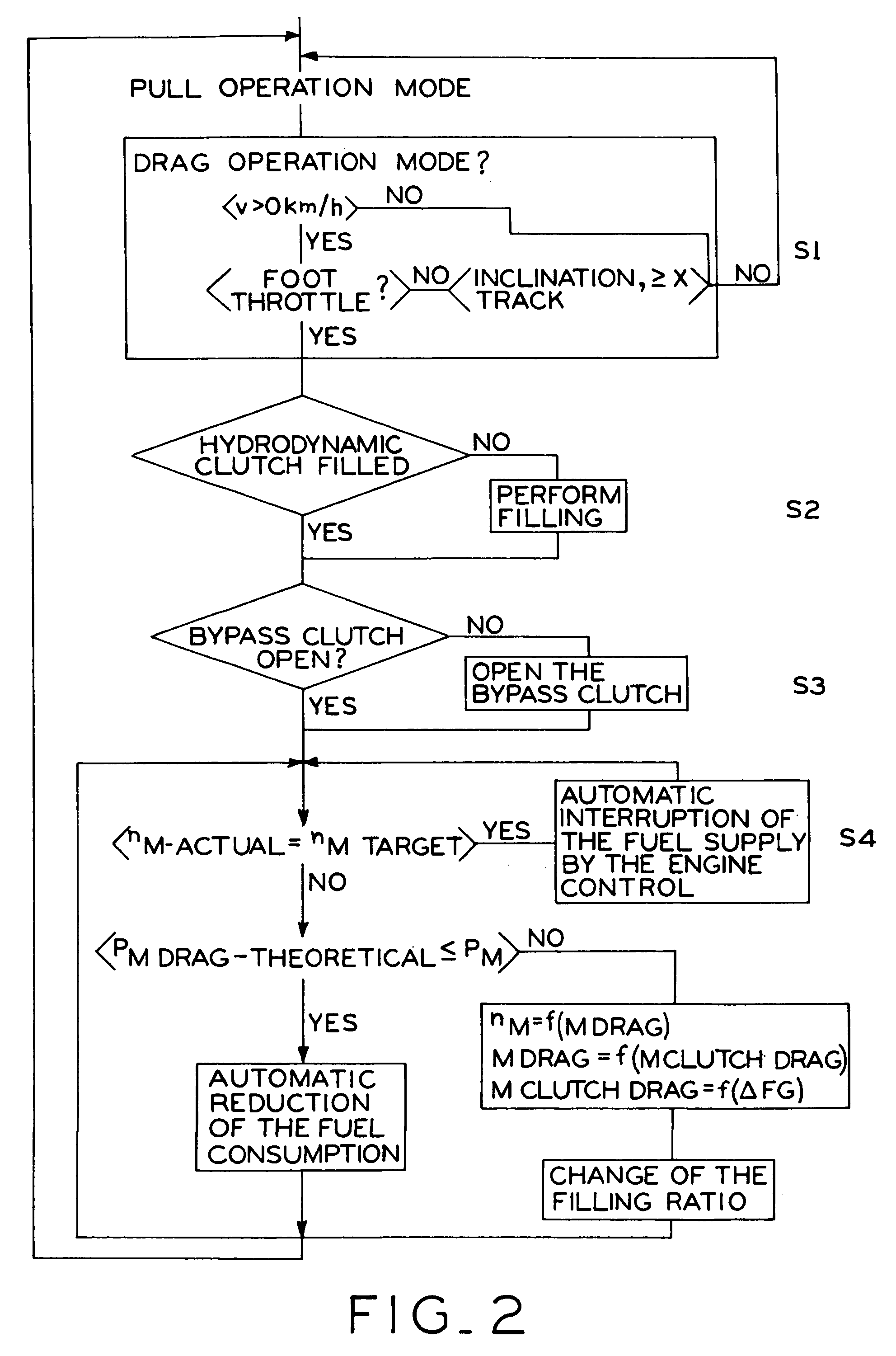
drag torque in a drive train that comprises an internal-combustion engine and a gearbox unit which can be coupled to the same, and further comprising a regulatable clutch between the gearbox unit input and the gearbox unit output, whose drive side is connected, at least indirectly, with the gearbox unit input, and whose output side is connected, at least indirectly, with the gearbox unit output, is characterized in that, during a drag operation mode phase, the power introduced from the wheels into the drive train of the vehicle is transferred by the regulatable clutch. The moment transferred by the clutch is controlled or regulated in such a way that the drive engine connected to the gearbox unit is operated at a rotational speed nM-Reference which is equal to or greater than the idling rotational speed nIdle-Run. This design has the advantage that the fuel supply of the engine is reduced or automatically and completely interrupted. The reduction or complete interruption of the fuel supply depends on whether the power introduced into the vehicle and theoretically available for the internal-combustion engine to drive the system in drag (push) operation mode or pull operation mode is, indeed, sufficient to operate the internal-combustion engine at idling rotational speed or at a higher rotational speed.
[0007]The solution provided by the present invention has the advantage of a substantial reduction in fuel consumption as compared with the conventional arrangement in a mechanical drive train with a permanent coupling. This advantage results from the fact that the vehicle is not delayed by an unnecessarily high drag torque of the internal-combustion engine due to the rotational speed resulting from the transmission of the gearbox. Thus, a vehicle riding uphill or on level terrain behaves similarly to how it does when idling. This method can be applied without any restrictions for rides over level terrain with little or no additional acceleration of the vehicle. In accordance with a further advantageous development of the method designed by this invention, this method can also be modified and applied to downhill rides by adjusting the appropriate control of the transferable moment of the clutch to ensure a ride with an almost constant speed vconstant, or at least to prevent the vehicle from accelerating greatly. The rotational speed of the internal-combustion engine is regulated in dependence on the desired travel speed, while taking into consideration the transmission unit arranged between the internal-combustion engine and the wheels and the connected transmission ratios. This solution allows one to keep a constant speed, in a simple manner, even during the drag operation mode phase and to adjust this speed to the concrete requirements, while optimally utilizing the available engine drag torque.
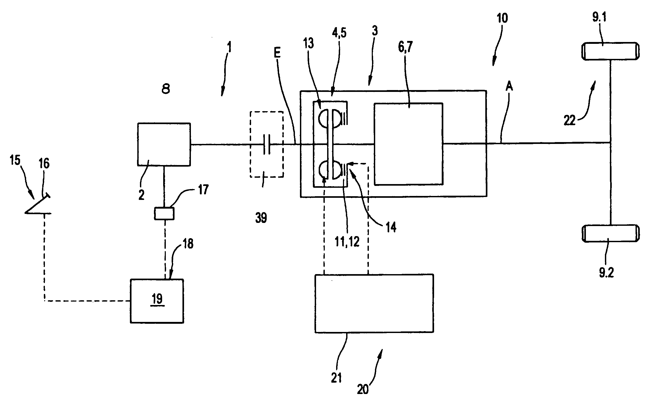
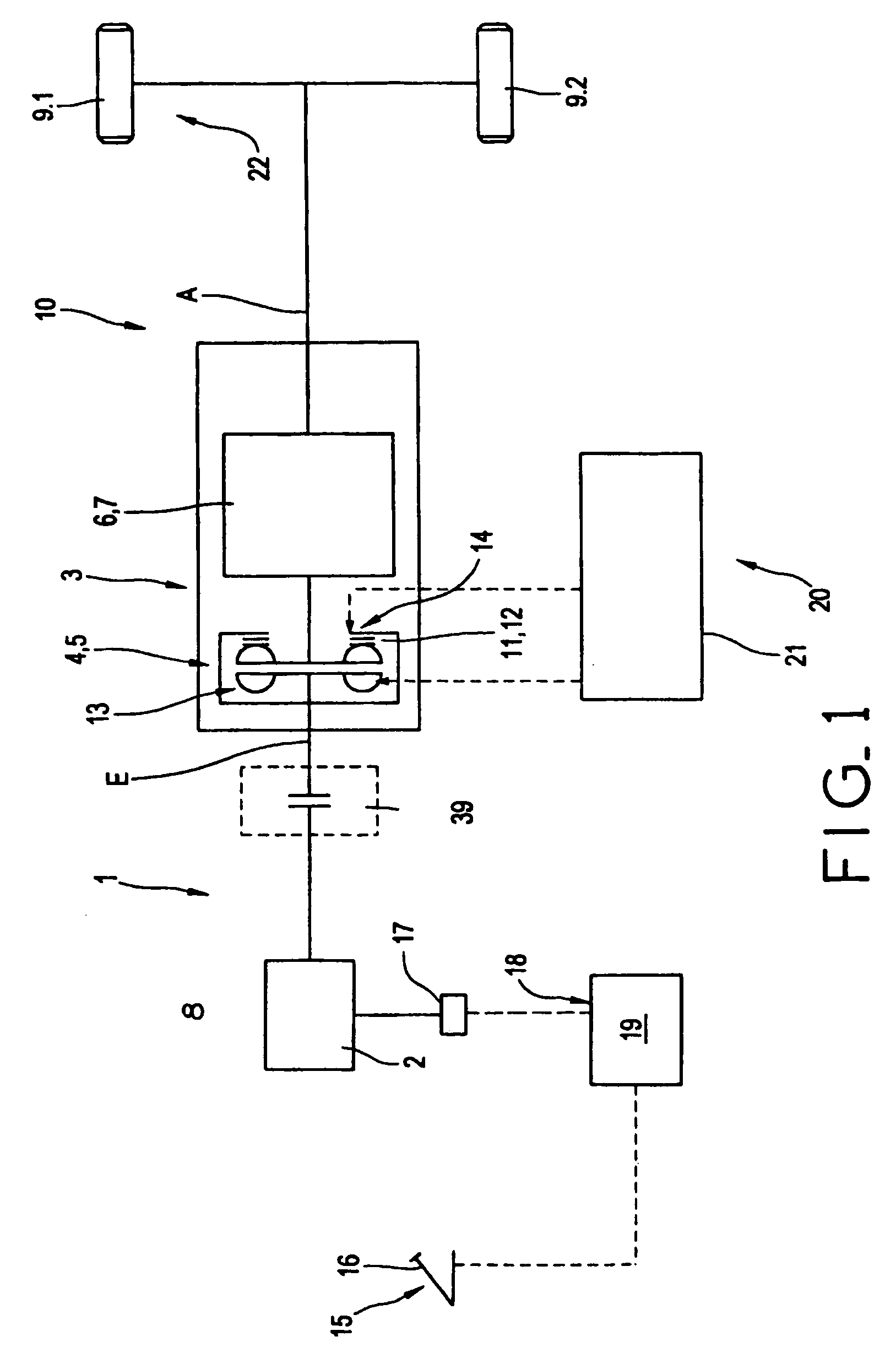
[0008]According to an especially advantageous embodiment of the invention, the method for controlling and / or regulating the drag torque is implemented in a drive train that comprises a drive engine and a gearbox unit, which can be coupled to the drive train, which further comprises a hydrodynamic clutch and a bypass clutch, which can be connected in parallel, and the bypass clutch serves the purpose of the mechanical coupling between the primary and secondary wheels of the hydrodynamic clutch. During the drag operation mode phase, the power introduced by the wheels into the vehicle, and especially into the drive train, is transferred by the hydrodynamic clutch. For this purpose, the bypass clutch is deactivated. Furthermore, according to the invention, the moment transmitted by the hydrodynamic clutch is controlled and regulated by changing the mass flow, and especially the filling ratio, in such a way that the drive engine connected to the input of the gear unit, and thus to the drive side of the hydrodynamic clutch, is operated at a rotational speed equal to or greater than the idling rotational speed, and thus the fuel supply to the internal-combustion engine is reduced or automatically and completely disconnected. Due to the hydrodynamic power transmission, the drag torque is controlled free of wear. The drive side of the hydrodynamic clutch is formed by the bucket wheel, which, during the transmission of the power from the drive engine to the gearbox unit output, functions as an impeller.

Problems solved by technology

However, it requires the actuation of at least one control element, and the drag operation mode itself cannot be influenced, especially in regards to the speed of the vehicle.
When travelling downhill, this solution is especially disadvantageous, because it does not allow one to utilize the braking moment of the inertia of the internal-combustion engine.
Furthermore, in this design, the internal-combustion engine is always uncoupled, irrespective of whether the engine braking moment can be utilized positively or negatively.

Method used


Image

  • Method for controlling and/or regulating the braking torque in a drive train, and control and regulating system
  • Method for controlling and/or regulating the braking torque in a drive train, and control and regulating system
  • Method for controlling and/or regulating the braking torque in a drive train, and control and regulating system

Examples


Embodiment Construction

[0036]FIG. 1 illustrates, in schematically simplified representation, a drive system 1, in which the method according to the invention is implemented in a particularly advantageous manner. The system comprises an internal-combustion engine 2, and a gearbox unit 3 that can be mechanically connected to it. The gearbox unit is designed as an automatic gearbox. In this type of gearbox, the power between the gearbox unit and the drive engine can be completely interrupted during the gear-changing process. The gearbox unit 3 comprises an initiating element 4 in the form of a regulatable clutch 26 (FIG. 5)—here a hydrodynamic clutch—and a gear component 6, which is coupled to this starting element 4, and which can have the form of subsequently arranged stages. The drive end of the initiating element 4—marked here with 8—is connected with the gearbox input E—seen in the force flow direction in traction operation from the internal-combustion engine towards the drive. The output of the subsequ...


PUM


Abstract

The aim of the invention is to regulate the braking torque in a drive train comprising an internal combustion engine (2) and a gearbox unit (3) which can be coupled to the same, using a regulatable clutch (5). To this end, the power introduced by the wheels into the drive train of the vehicle is transmitted via the regulatable clutch (5), in the overrun condition. The torque which can be transferred via the regulatable hydrodynamic clutch is controlled or regulated in such a way that the drive motor connected to the gearbox unit is operated at a rotational speed nm-soil which is equal to or larger than the idling rotational speed nLeerlauf.

Description

CROSS-REFERENCE TO RELATED APPLICATION [0001]This application is related to and claims the benefit under 35 U.S.C. §119 and 35 U.S.C. §365 of International Application No. PCT / EP2002 / 10360, filed Sep. 16, 2002.BACKGROUND OF THE INVENTION[0002]The invention relates to a method for controlling and / or regulating the drag torque in a drive train. More specifically, the invention relates to a control and / or regulating system that is assigned to a drive train for controlling and / or regulating the drag torque.[0003]Methods for regulating the drag moment in drive trains of various designs are well known, and these especially include diesel-electric drive trains, but also conventional mechanical drive trains in various forms. In a conventional drive train with an internal-combustion engine and a mechanical drive train that comprises a gearbox unit connected to the engine, during the drag operation mode phase, a reversal of the energy flow occurs, i.e., power from the wheels is introduced int...

Claims


Application Information

Patent Timeline
IPC IPC(8): B60W10/02B60W10/06B60W30/18B60W50/00F16D48/06F16H61/14F16H61/21
CPCB60W10/06B60W30/18F16H61/143F16H61/21B60W10/02B60K2741/025Y10T477/755B60W2050/0045B60W2540/10B60W2540/103B60W2550/142B60W2710/0644B60W2710/065Y02T10/52F16H2059/663Y10T477/679Y10T477/78B60W10/04B60W30/1819Y02T10/84B60W2552/15Y02T10/40
Inventor DIETZEL, BERND
Owner VOITH TURBO GMBH & CO KG
Why Eureka
Try Eureka