Refrigerant circuit and heat pump type hot water supply apparatus
a heat pump and circuit technology, applied in heat pumps, lighting and heating apparatus, compression machines with several condensers, etc., to achieve the effect of ensuring energy saving
- Summary
- Abstract
- Description
- Claims
- Application Information
AI Technical Summary
Benefits of technology
Problems solved by technology
Method used
Image
Examples
first embodiment
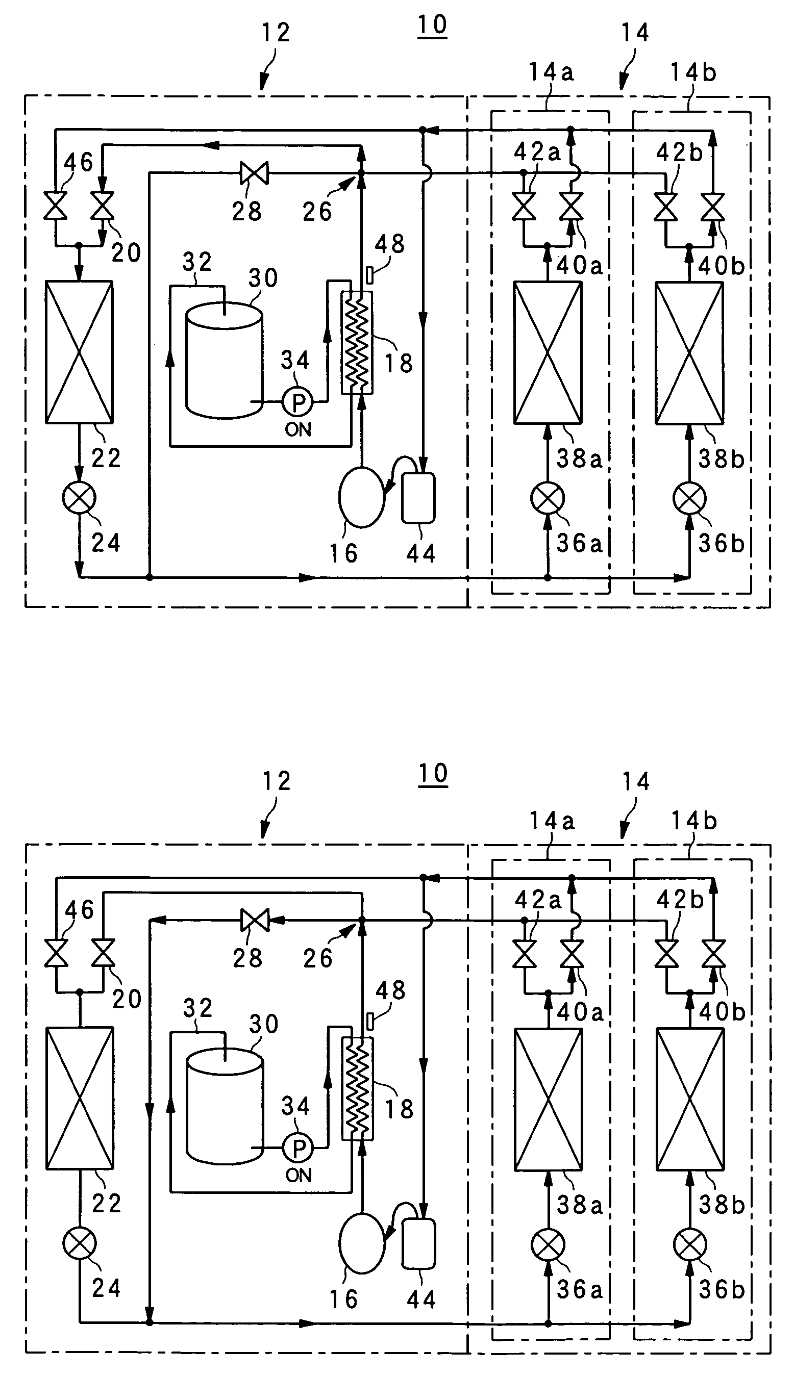
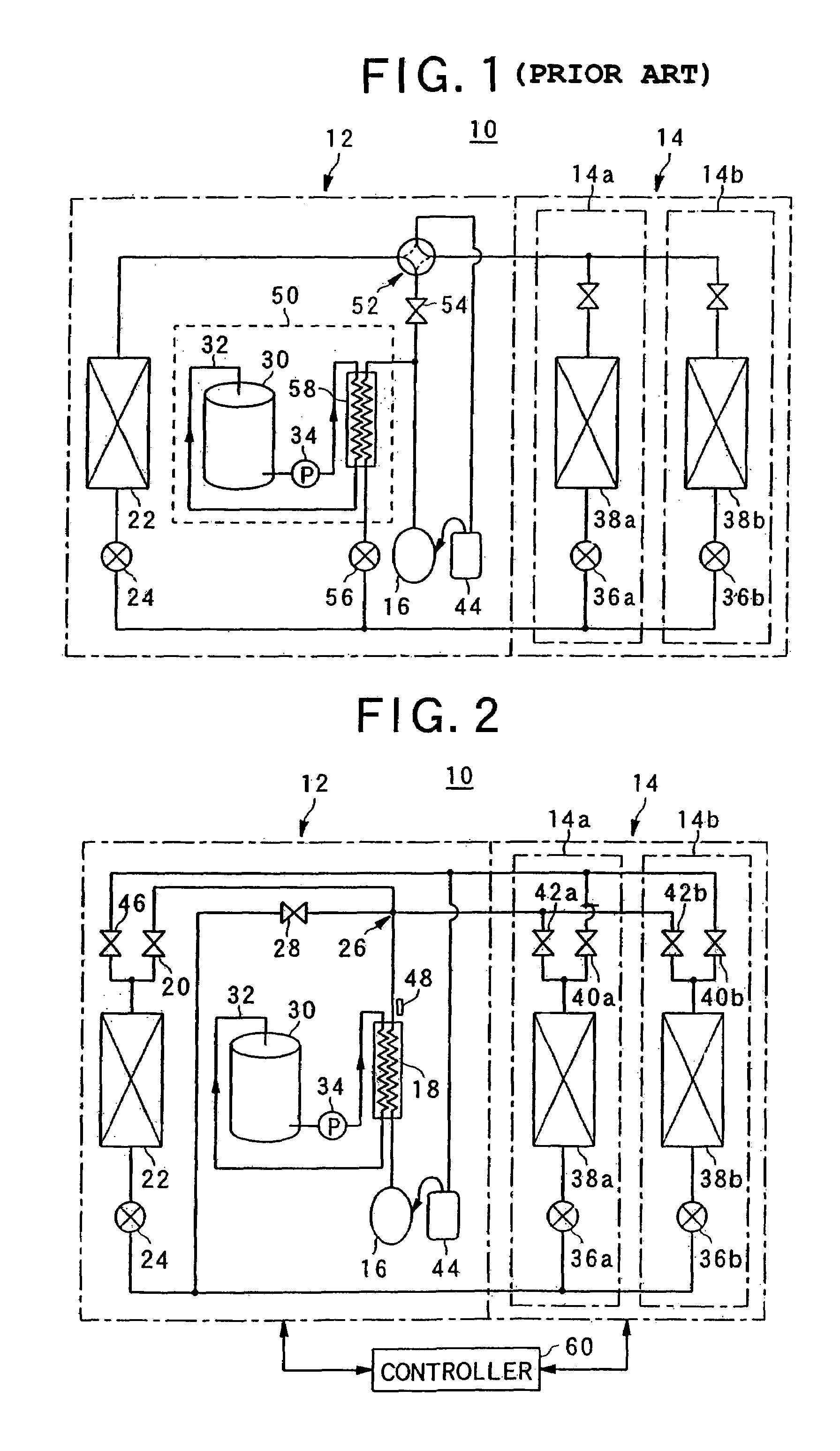
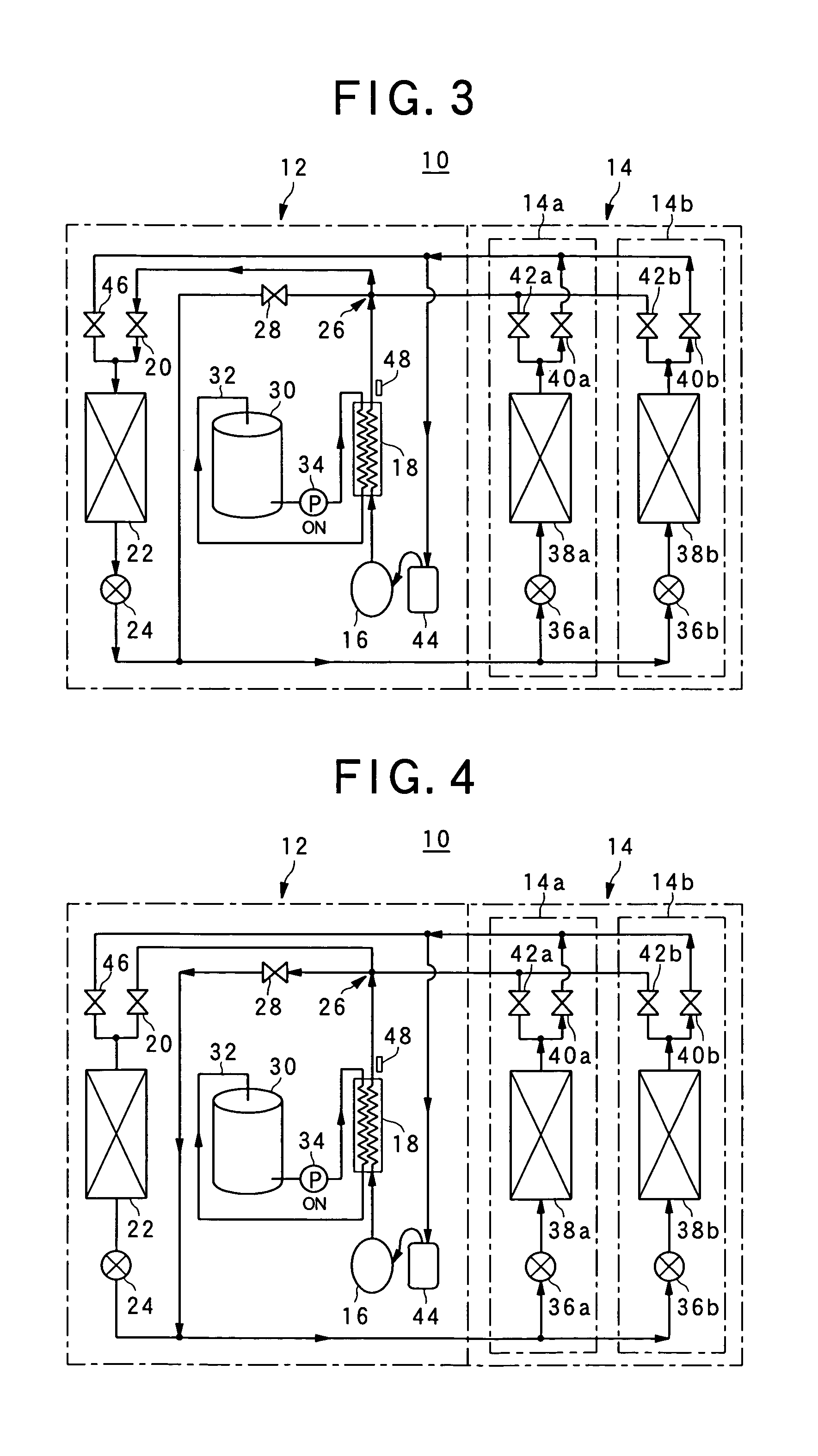
[0038]Under cooling operation, the first and second expansion valves 24, 36a, 36b are opened, the first and fourth electromagnetic valves 20, 40a, 40b are opened, and the second, third and fifth electromagnetic valves 46, 28, 42a and 42b are closed as shown in FIG. 3. The refrigerant discharged from the compressor 16 is once cooled in the gas cooler 18, and reaches the four-way branched passage 26. Here, since the third and the fifth electromagnetic valves 28, 42a and 42b are closed, the refrigerant flows to the first electromagnetic valve 20, and is further cooled and condensed in the outdoor heat exchanger 22. The refrigerant thus condensed flows from the first expansion valve 24 to the second expansion valves 36a and 36b because the third electromagnetic valve 28 is closed, and is evaporated in the indoor heat exchangers 38a and 38b. The evaporation of the refrigerant in the indoor heat exchangers 38a and 38b allows the user-side units 14a and 14b to carry out the cooling operati...
second embodiment
[0043]When the heating operation is carried out, as shown in FIG. 5, the first and second expansion valves 24, 36a, 36b are opened, the first, third and fourth electromagnetic valves 20, 28, 40a, 40b are closed, and the second and fifth electromagnetic valves 46, 42a, 42b are opened. In this case, the refrigerant discharged from the compressor 16 is passed through the gas cooler 18. Conversely to the cooling operation, the first and third electromagnetic valves 20 and 28 are closed, so that the refrigerant flows into the fifth electromagnetic valves 42a and 42b and then is condensed in the indoor heat exchangers 38a, 38b. The condensation of the refrigerant in the indoor heat exchangers 38a and 38b allow the user-side unit 14 to carry but the heating operation. When only one indoor unit is driven to carry out the heating operation, the fifth electromagnetic valve 42 of the indoor unit which is not driven is closed.
[0044]The refrigerant condensed in the indoor heat exchangers 38a, 38...
third embodiment
[0046]When only the hot water supply operation is needed, as shown in FIG. 6, the first expansion valve 24 is opened, the second expansion valves 36a and 36b are closed, the first and fifth electromagnetic valves 20, 42a and 42b are closed, the first and fifth electromagnetic valves 20, 421a, 42b are closed, and the second, third and fourth electromagnetic valves 46, 28, 40a, 40b are opened. Therefore, the refrigerant is circulated in the heat-source side unit 12, and thus no refrigerant flows in the user-side unit 14.
[0047]The refrigerant discharged from the compressor 16 is heat-exchanged with water in the gas cooler 18, and condensed therein. The refrigerant thus condensed reaches the four-way branch passage 26, and flows to the third electromagnetic valve 28 because the first and fifth electromagnetic valves 20, 42a and 42b are closed. Thereafter, the condensed refrigerant reaches the refrigerant pipe through which the first and second expansion valves 24, 36a and 36b are connec...
PUM
 Abstract
Description
Claims
Application Information
 - R&D
- Intellectual Property
- Life Sciences
- Materials
- Tech Scout
- Unparalleled Data Quality
- Higher Quality Content
- 60% Fewer Hallucinations
Browse by: Latest US Patents, China's latest patents, Technical Efficacy Thesaurus, Application Domain, Technology Topic, Popular Technical Reports.
© 2025 PatSnap. All rights reserved.Legal|Privacy policy|Modern Slavery Act Transparency Statement|Sitemap|About US| Contact US: help@patsnap.com


