
Snow cycle

a technology of snow cycle and sled, which is applied in the field of snow cycle, can solve the problems of increasing the cost and complexity of the manufacture and operation of such snow vehicles, losing traction and steering control, etc., and achieves the effect of improving steering and performance and quickly changing

Inactive Publication Date: 2007-02-27
KEINATH MARK B +1
View PDF31 Cites 60 Cited by
  • Summary
  • Abstract
  • Description
  • Claims
  • Application Information

AI Technical Summary

Benefits of technology

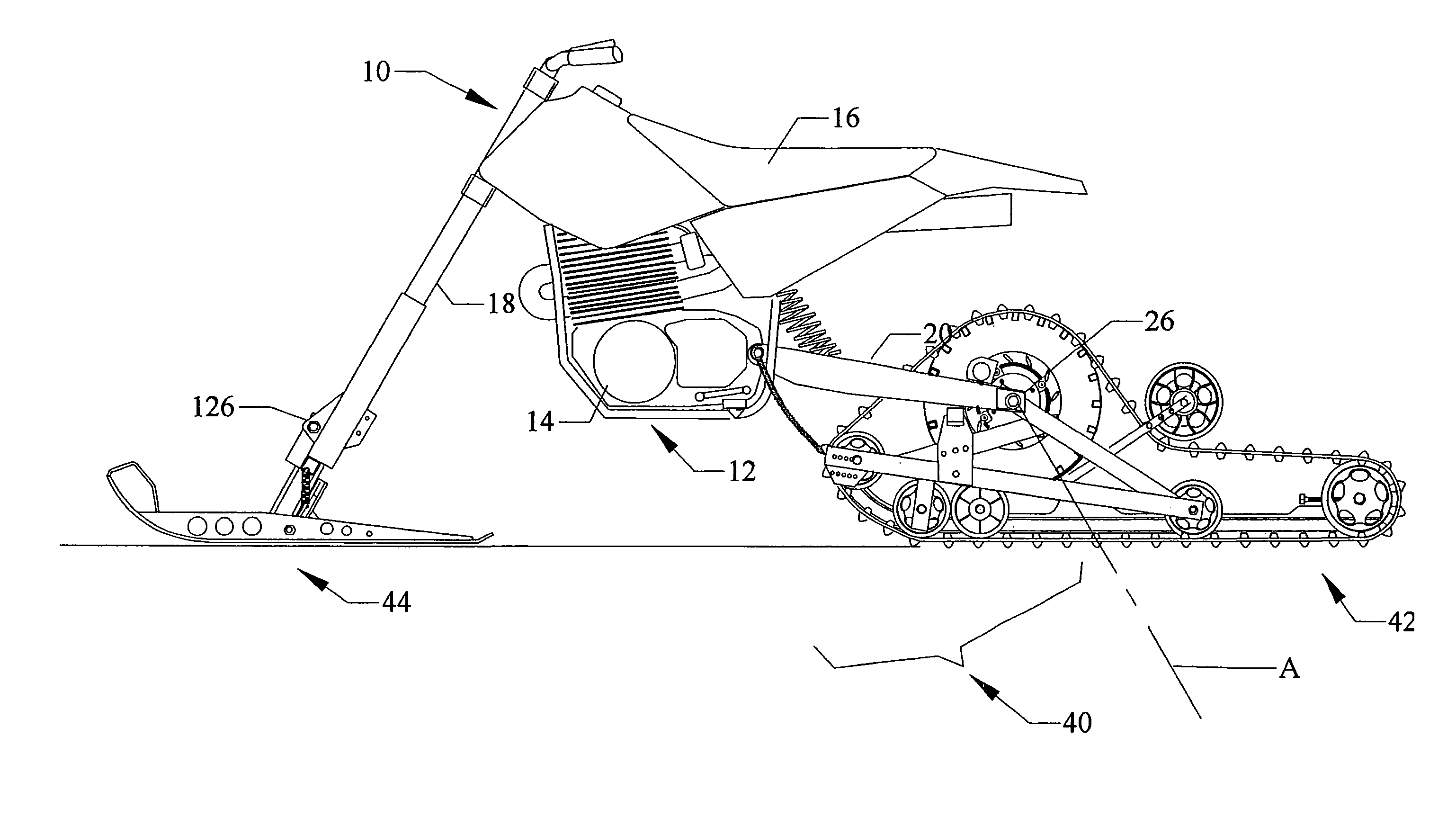
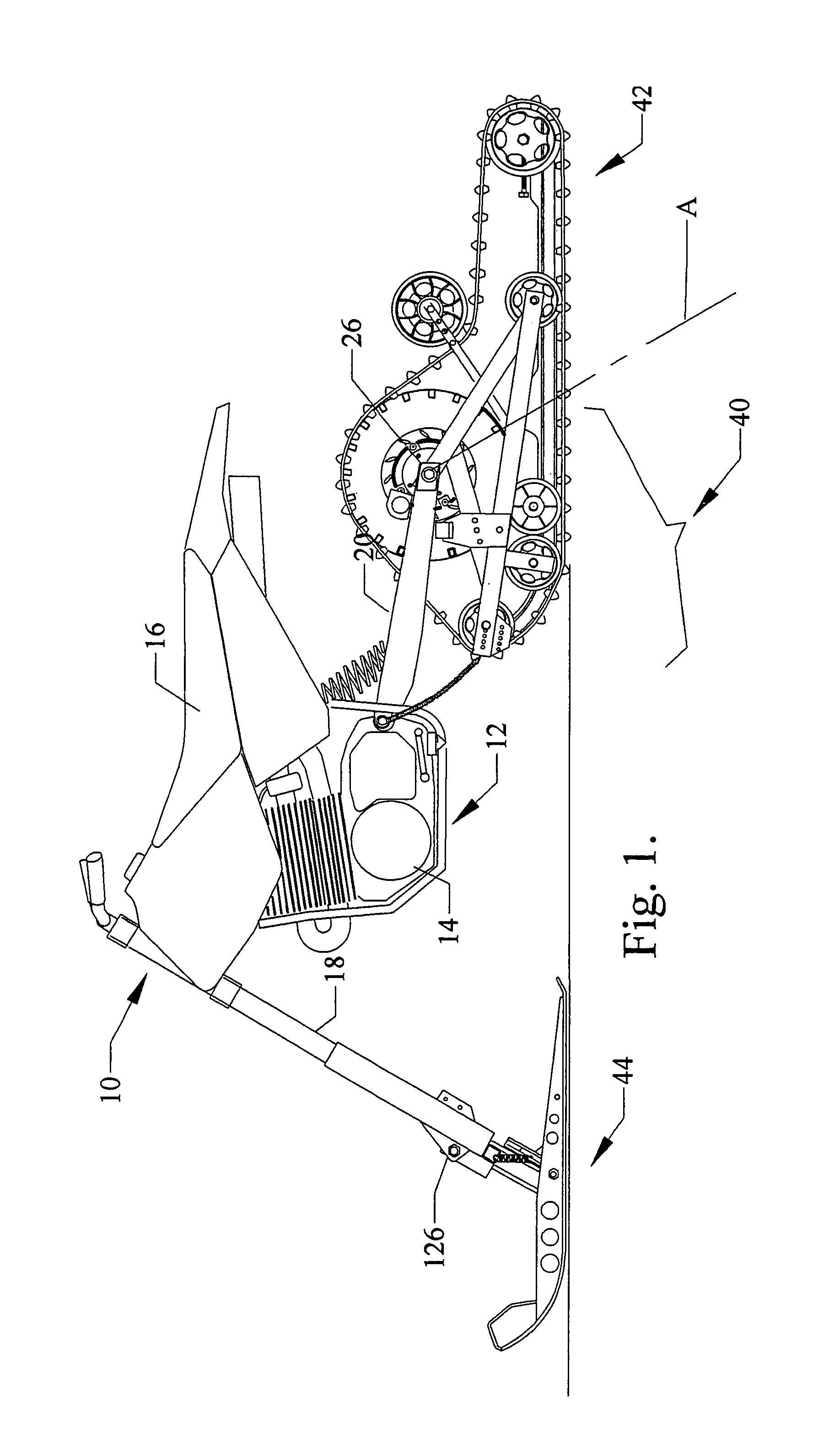
[0008]The invention also contemplates a snow conversion kit for a motorcycle which includes the snow track assembly and ski assembly above. The invention has the advantage of providing a snow cycle with a front ski assembly which is pivotable about two transverse axis, enabling the front ski assembly to pivot up and down in the usual manner, but also enable the front ski assembly to tilt from side to side relative to the forks, such that when the snow cycle is leaned to one side when making an aggressive turn, the ski assembly remains fully and flatly in contact with the snowy terrain.
[0009]According to a preferred embodiment, the front ski assembly includes two skis which are pivotable in the up and down direction independently of one another, yet tiltable from side to side relative to the forks together as a unit. Such a ski assembly provides enhanced steerability and performance to such snow cycles.
[0010]The invention has the further advantage of enabling the front ski assembly and rear snow track device to be mounted on an otherwise conventional motorcycle without substantial or any modification of the existing mounting points and structure associated with mounting the wheels of the motorcycle. As such, the owner of a motorcycle having a set of wheels along with the subject snow conversion kit can quickly change between the wheels and kit with little or no modification to the motorcycle swing arm and chain drive system or to the front forks.

Problems solved by technology

Such modification and requirement for replacement of the swing arm adds considerable cost and complexity to the manufacture and operation of such snow vehicles.
Such tilting of the motorcycle has the effect of rolling the front ski toward one edge or the other, causing the ski to come out of full contact with the ground, thus losing traction and control of steering.

Method used


Image

  • Snow cycle
  • Snow cycle
  • Snow cycle

Examples


Embodiment Construction

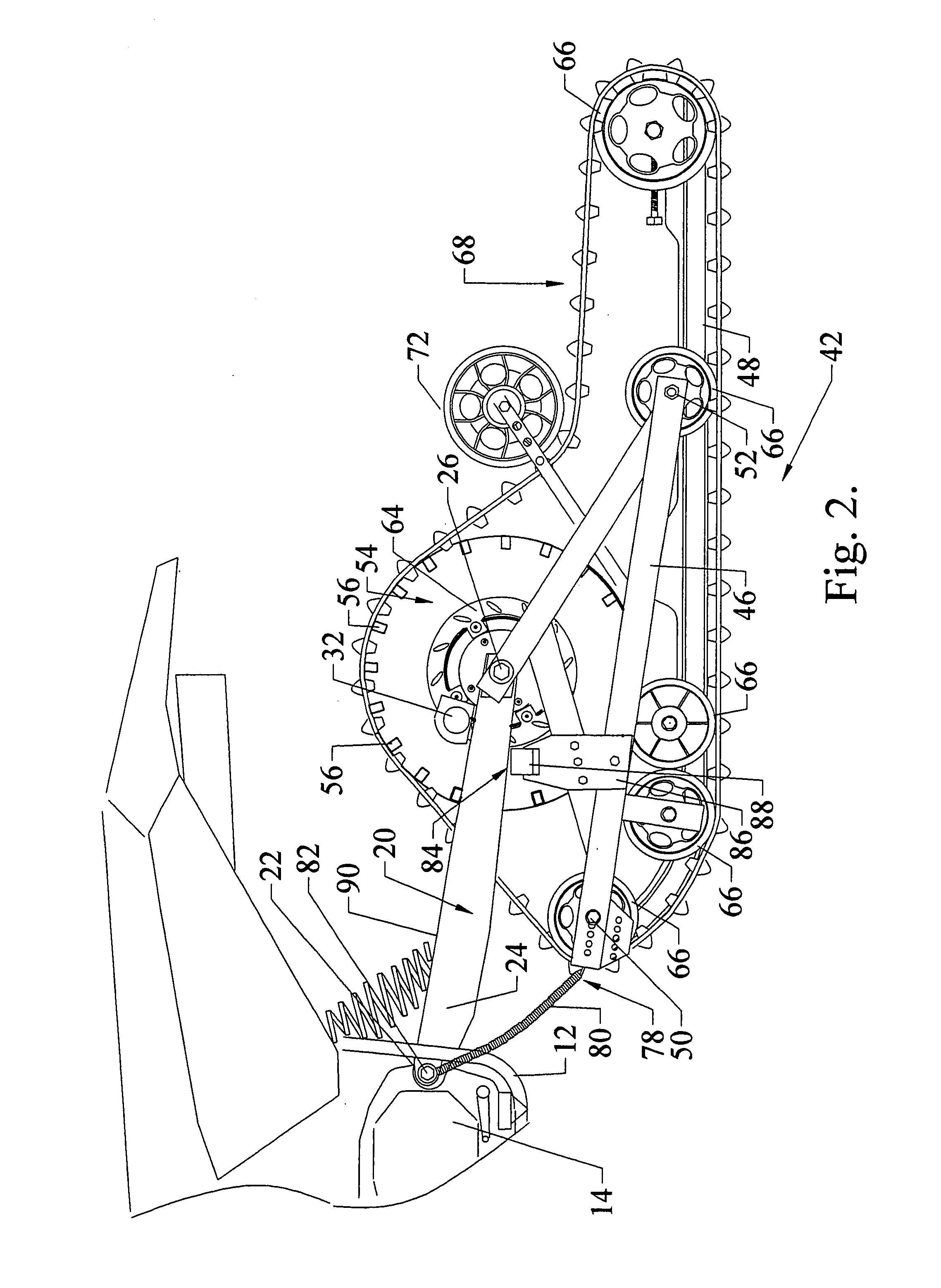
[0022]Referring to the enclosed drawings, a conventional off-road motorcycle vehicle 10 is shown having a frame 12 mounting an internal combustion engine 14, a seat 16 for an operator, and a set of steerable front forks 18. A rear swing arm 20 is pivoted at its forward end to the frame 12 by pivot connection 22 and includes a pair of laterally spaced arm portions 24 which extend rearwardly to free ends and support a transverse rear axle bolt 26 that is parallel to, but spaced from, the pivot connection 22 and is swingable with the swing arm 20 with up and down movement about an arc centered about an axis A of the pivot connection 22.

[0023]The engine 14 has an output shaft (not shown) on which a drive sprocket 28 is mounted. An endless, flexible drive chain 30 is entrained about and driven by the drive sprocket 28 for transmitting rotation of the sprocket 28 into driven rotation of the chain 30.

[0024]Normally, such motorcycle vehicles 10 are equipped with a rear wheel assembly (not s...


PUM


Abstract

A snow cycle includes a conventional motorcycle chassis having a set of steerable front forks and a rear swing arm, which normally mount front and rear wheels of the cycle, respectively. A snow track module is mounted to the rear swing arm and has an endless track driven by a cog connected to a drive sprocket of the engine by a single chain. At least one and preferably a pair of skis are mounted off the front forks and are pivotable fore and aft as well as tiltable to either side to maintain the ski flat to the ground when the vehicle is tilted to one side or the other when making an aggressive turn.

Description

[0001]The disclosure incorporates the snow cycle disclosed in provisional patent application 60 / 349,007, filed Jan. 14, 2002 whose priority is claimed for this application.BACKGROUND OF THE INVENTION[0002]1. Technical Field[0003]This invention relates generally to motorcycles equipped with a rear track and front skis to enable the motorcycle to travel in snow, and to conversion kits for such motorcycles.[0004]2. Related Art[0005]Snow vehicles having substantially the same upper frame structure as that of a motorcycle are know to the art to be equipped with an endless track mounted at the rear of the vehicle in place of the rear drive wheel, and a steering ski mounted at the front portion in place of the front wheel. Such a vehicle is disclosed, for example, in U.S. Pat. No. 5,474,146. In this case, the swing arm of the motorcycle is removed and replaced with a modified swing arm mounting an intermediate set of transfer sprockets which connect the drive hub of the endless track to th...

Claims


Application Information

Patent Timeline
IPC IPC(8): B62M27/02
CPCB62M27/02B62M2027/021
Inventor KEINATH, MARK B.KEINATH, JOHN E.
Owner KEINATH MARK B
Learn More