
Electrodynamic position transducer with electronic memory means

Inactive Publication Date: 2007-02-20
ELBI INT
View PDF6 Cites 15 Cited by
  • Summary
  • Abstract
  • Description
  • Claims
  • Application Information

AI Technical Summary

Benefits of technology

[0011]One object of the present invention is to provide a transducer of the type defined above, the calibration of which can conveniently be carried out electronically, without the need to adjust the position of the adjustment members mechanically, thereby making it possible drastically to simplify the mechanical structure of the transducer itself.

Problems solved by technology

One problem which is encountered with such transducers consists in the initial calibration of their transduction characteristics.
In order to be able to achieve this calibration mechanically, the structure of prior art transducers is necessarily complex.
In addition, the calibration operation is laborious and subject to possible changes over time.

Method used


Image

  • Electrodynamic position transducer with electronic memory means
  • Electrodynamic position transducer with electronic memory means
  • Electrodynamic position transducer with electronic memory means

Examples


Embodiment Construction

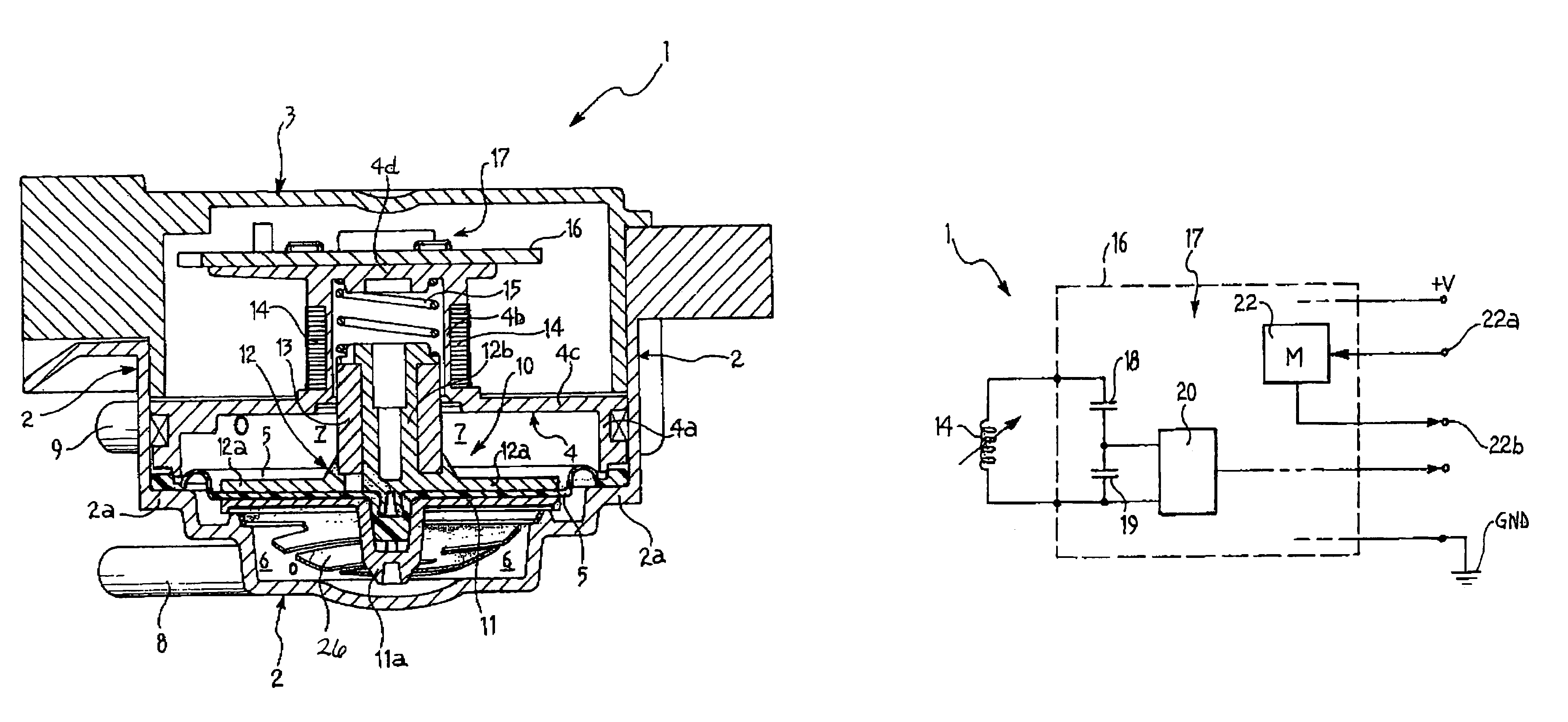
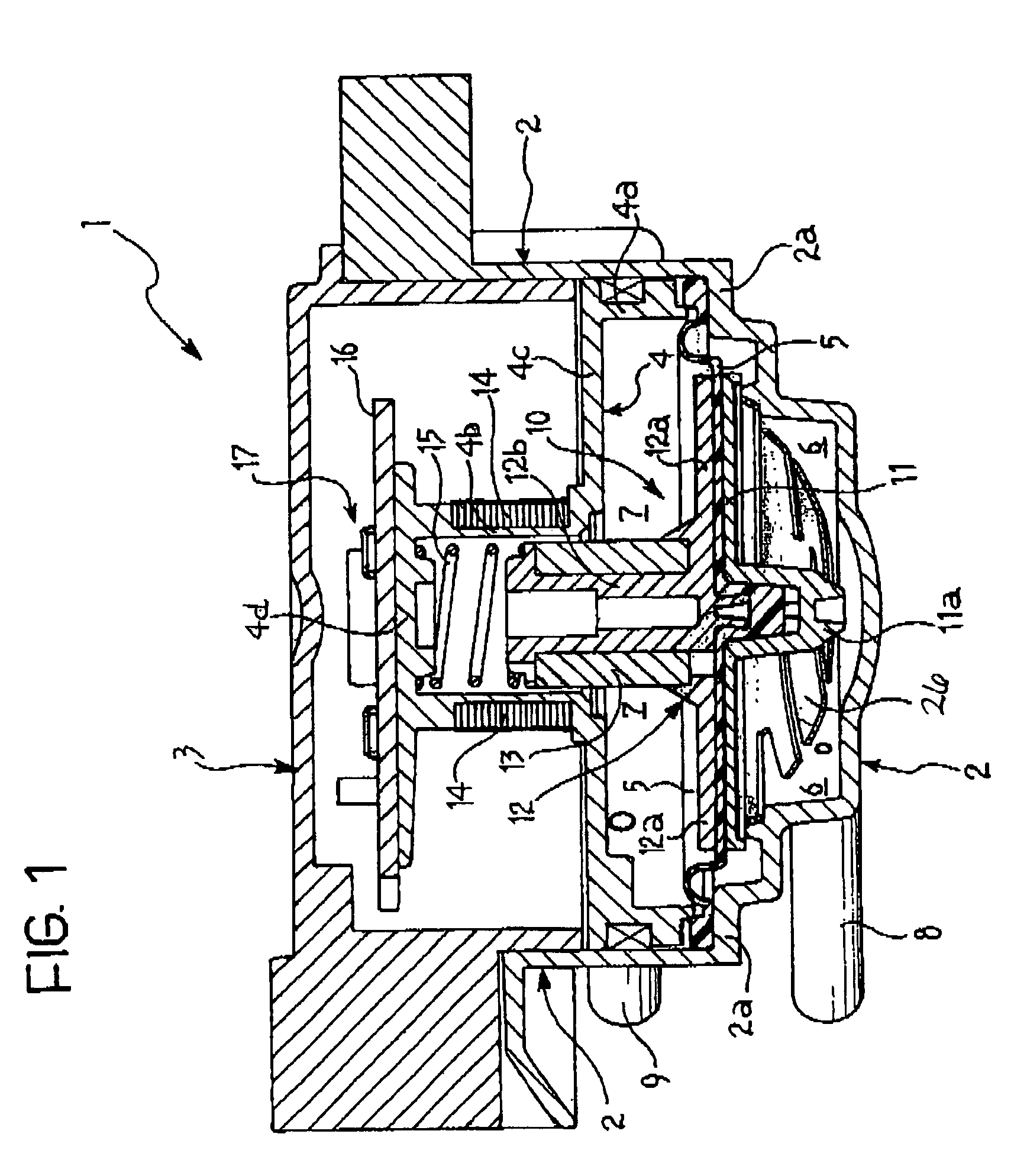
[0016]In FIG. 1, a transducer according to the invention is generally indicated 1.

[0017]In the embodiment illustrated by way of example, the transducer 1 is operable to act as a pressure transducer, of differential type. Moreover, as will become more apparent hereinbelow, the invention is not limited to this type of transducer.

[0018]In the embodiment given by way of example, the transducer 1 comprises a rigid casing formed by a first element 2, substantially in the shape of a cup, and by a second element 3, also substantially cup shape and partially interpenetrated with the cup element 2.

[0019]Within the casing of the transducer 1, a support body, generally indicated 4, is interposed between the elements 2 and 3. This body has a lower annular portion 4a and an upper tubular portion 4b, joined together by a transverse annular wall 4c.

[0020]The tubular portion 4b of the support body 4 is closed at one end by an end wall 4d.

[0021]A resilient membrane, constituted for example by an el...


PUM


Abstract

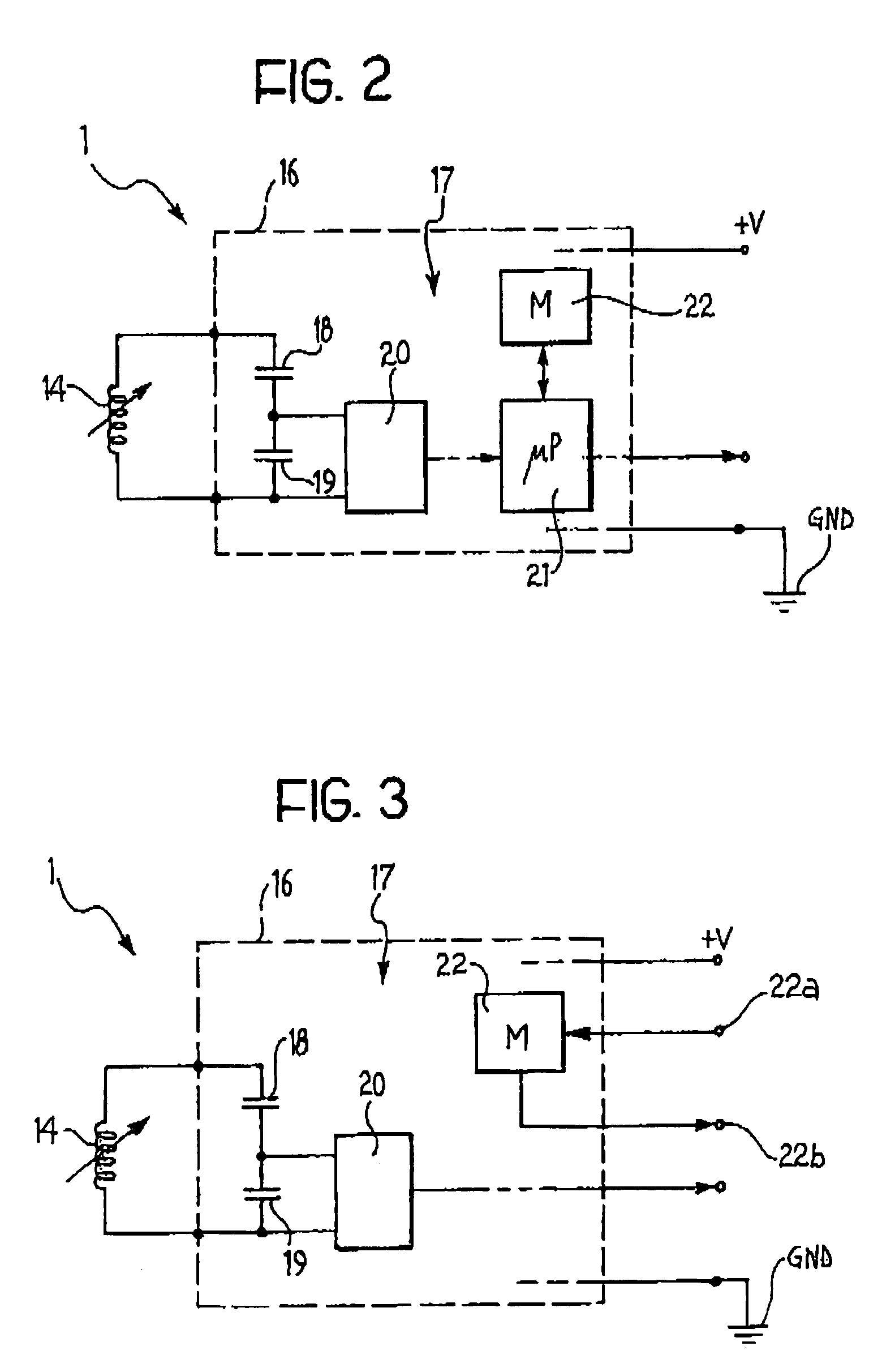
The transducer (1) comprises: a rigid casing (2–4) in which a membrane (5) is clamped which, together with a portion of the casing (2–4), defines at least one chamber (6, 7) of variable volume; at least one winding (14); an interaction element (13), able to interact magnetically with the winding (14) under the effect of a displacement of the membrane (5), in such a way that the inductance of the winding (14) is variable in dependence on the relative position of the interaction element with respect to the winding (14), and circuit devices (17) connected to the winding (14) and operable to supply electrical signals of which one parameter, frequency for example, is variable in dependence on the inductance of the winding (14); the said circuit devices (17) including a memory (22) operable to store data representative of corrective values which, when applied in operation to the effective instantaneous values of the said parameter, make it possible to obtain correct values of the parameter corresponding to a predetermined transduction characteristic.

Description

[0001]This is a National Stage entry of Application No. PCT / IB03 / 01070 filed Mar. 18, 2003; the disclosure of which is incorporated herein by reference.BACKGROUND OF THE INVENTION[0002]The present invention relates to an electrodynamic position transducer usable, for example, as a pressure transducer in a washing machine or a dishwasher, in a gas boiler or in a variety of domestic electrical appliances.[0003]The invention relates more specifically to a transducer including:[0004]a hollow rigid casing within which is clamped a membrane which, together with a portion of the casing, defines at least one chamber of variable volume;[0005]at least one winding;[0006]an interaction element operable to interact magnetically with the winding as a result of a displacement of the membrane, in such a way that the inductance of the said winding is variable in dependence on the relative position of the said element with respect to the winding, and[0007]circuit means connected to the said winding a...

Claims


Application Information

Patent Timeline
IPC IPC(8): G01B7/14A47L15/42D06F39/08G01L9/00G01L9/10H01F5/00
CPCA47L15/4244G01L9/10G01L9/007D06F39/087
Inventor BINDOCCI, SABRINADA PONT, PAOLOSENOR, PAOLOCARRER, GIORGIOGIORDANO, SERGIOMUNERETTO, ANGELO
Owner ELBI INT
Learn More