
Robot system having image processing function

a robot system and image processing technology, applied in the direction of electric programme control, program control, instruments, etc., can solve the problem that the robot hand cannot be placed to a suitable position/position

Inactive Publication Date: 2007-02-13
FANUC LTD
View PDF32 Cites 116 Cited by
  • Summary
  • Abstract
  • Description
  • Claims
  • Application Information

AI Technical Summary

Benefits of technology

[0006]An object of the present invention is to provide a robot system having an image processing function capable of determining an orientation and / or a position of a robot for performing an operation on an object by precisely detecting three-dimensional position and posture of individual objects in a randomly arranged stack or an aggregation in a container of a predetermined region, which have identical shapes and different three-dimensional positions / postures.

Problems solved by technology

The reason why individual workpieces having identical shapes and different three-dimensional positions / postures can not be picked out by a robot from a randomly arranged stack of workpieces or an aggregation of workpieces contained in a container is that the position / posture of individual workpieces in the stack or the aggregation can not be recognized, so that a robot hand can not be placed to a suitable position / posture at which the robot hand can hold the individual workpiece.

Method used


Image

  • Robot system having image processing function
  • Robot system having image processing function
  • Robot system having image processing function

Examples


Embodiment Construction

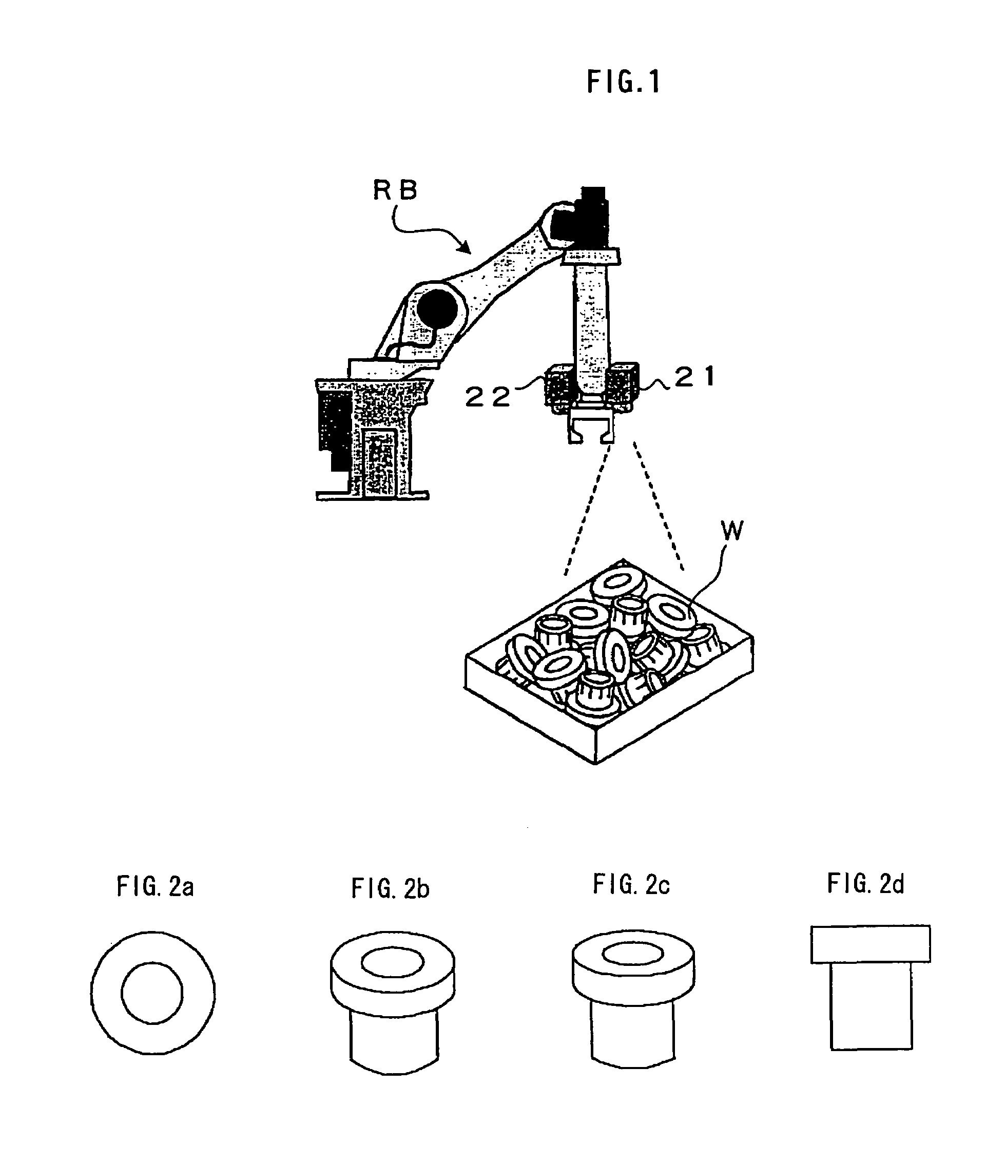
[0025]A robot system having an image processing function according to an embodiment of the present invention will be described. As shown in FIG. 1, a two-dimensional visual sensor 21 such as a CCD camera, as an image capturing device is attached to a wrist of a robot RB. In this embodiment, an image of a stack of workpieces, which are objects of detection having identical shapes and randomly arranged as shown in FIG. 1, is captured by the two-dimensional visual sensor 21, and orientation, or orientation and position of an operation to be performed by the robot RB are determined based on the captured image. Further, rough position and posture of the individual workpieces are detected to determine the orientation of the robot based on the captured image and then precise position and posture of the workpiece are detected by the two-dimensional visual sensor 21 or a three-dimensional visual sensor 22.

[0026]For this purpose, images of a reference object, which is one of workpieces W subj...


PUM


Abstract

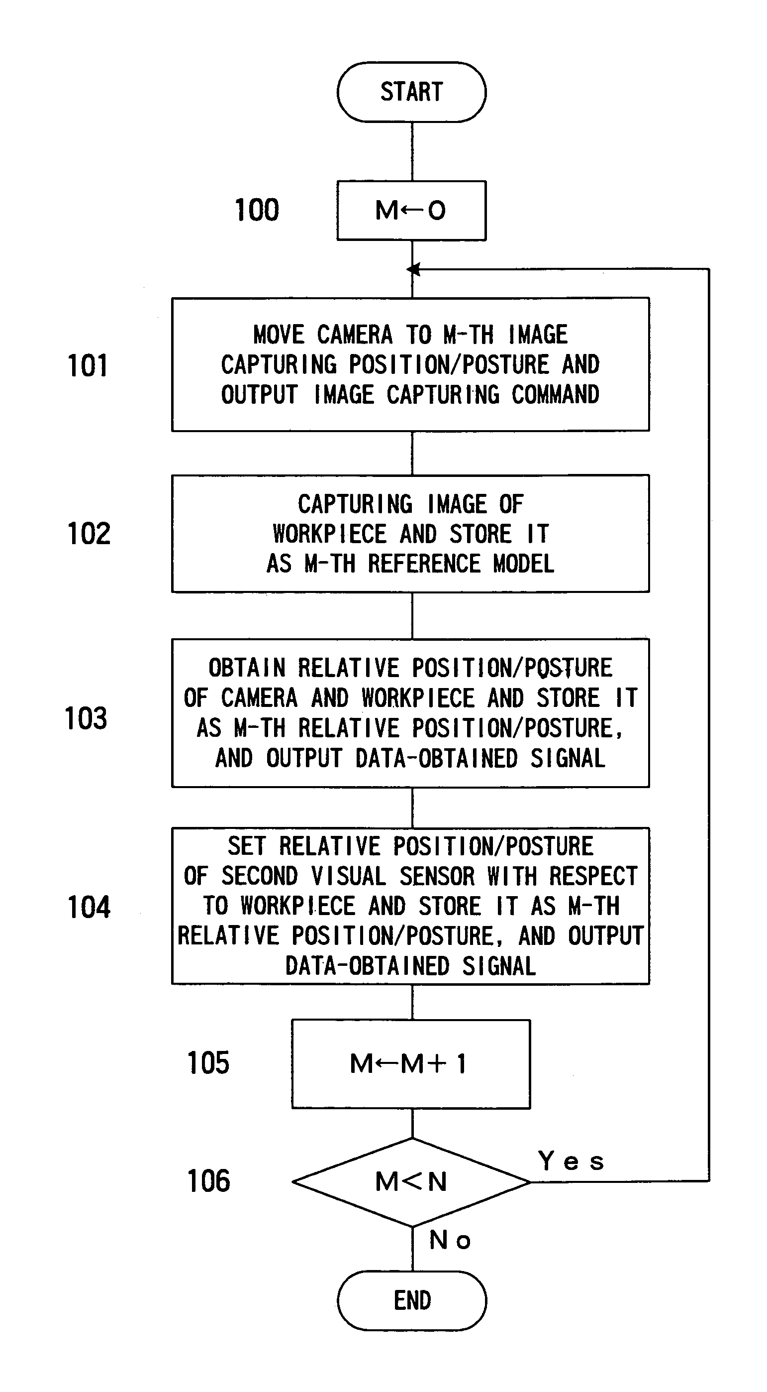
A robot system having an image processing function capable of detecting position and / or posture of individual workpieces randomly arranged in a stack to determine posture, or posture and position of a robot operation suitable for the detected position and / or posture of the workpiece. Reference models are created from two-dimensional images of a reference workpiece captured in a plurality of directions by a first visual sensor and stored. Also, the relative positions / postures of the first visual sensor with respect to the workpiece at the respective image capturing, and relative position / posture of a second visual sensor to be situated with respect to the workpiece are stored. Matching processing between an image of a stack of workpieces captured by the camera and the reference models are performed and an image of a workpiece matched with one reference model is selected. A three-dimensional position / posture of the workpiece is determined from the image of the selected workpiece, the selected reference model and position / posture information associated with the reference model. The position / posture of the second visual sensor to be situated for measurement is determined based on the determined position / posture of the workpiece and the stored relative position / posture of the second visual sensor, and precise position / posture of the workpiece is measured by the second visual sensor at the determined position / posture of the second visual sensor. A picking operation for picking out a respective workpiece from a randomly arranged stack can be performed by a robot based on the measuring results of the second visual sensor.

Description

BACKGROUND OF THE INVENTION[0001]1. Field of the Invention[0002]The present invention relates to a robot system having an image processing function of detecting three-dimensional position and posture (orientation) of an object, and in particular to a robot system having an image processing function suitable for a bin-picking operation of taking out a workpiece one by one from a randomly arranged stack of workpieces.[0003]2. Description of Related Art[0004]An operation of taking out an individual workpiece form a randomly arranged stack of workpieces or an aggregation of workpieces contained in a container of a predetermined size, which have identical shapes and different three-dimensional positions / postures, have been performed manually. In storing workpieces in a pallet or placing workpieces at a predetermined position in a machine or a device using a (dedicated) robot, since it has been impossible to directly take out an individual workpiece one by one from the randomly arranged s...

Claims


Application Information

Patent Timeline
IPC IPC(8): G06K9/00B25J19/04B25J9/16B25J9/22B25J13/08G05B19/19G06T1/00G06T7/00G06T7/60
CPCB25J9/1697G05B2219/37553G05B2219/37555G05B2219/40613G05B2219/39393G05B2219/40053G05B2219/37567
Inventor WATANABE, ATSUSHIARIMATSU, TARO
Owner FANUC LTD
Learn More