
Image display apparatus with driving modes and method of driving the same

a technology of image display and driving mode, which is applied in the direction of photosensitive materials, instruments, printers, etc., can solve the problems of shortening double scan driving systems needing larger power consumption than single scan driving systems, and reducing the life of organic el elements, etc., to achieve the effect of power consumption

Inactive Publication Date: 2007-02-13
SAMSUNG DISPLAY CO LTD
View PDF34 Cites 30 Cited by
  • Summary
  • Abstract
  • Description
  • Claims
  • Application Information

AI Technical Summary

Benefits of technology

[0018]An object of the present invention is to provide an image display apparatus in which power consumption and brightness can be adjusted, and a method of driving the same.
[0019]Another object of the present invention is to provide an image display apparatus in which power consumption and brightness can be adjusted in accordance with a request from a user, and a method of driving the same.
[0020]Still another object of the present invention is to provide an image display apparatus, in which power consumption and brightness can be adjusted in accordance with the peripheral circumstances, a power remaining quantity or a display content, and a method of driving the same.

Problems solved by technology

In viewpoint of the brightness, it is difficult to view the display apparatus in a situation other than a dark situation like night.
Also, the double scan driving system needs the power consumption larger than the single scan driving system.
In this method, however, the increase of the drive voltage shortens a life of the organic EL element.
Therefore, the circuit structure becomes complicated and the control becomes complicated.
As a result, the cost of the product increases.
However, the circuit for changing the pulse duration is complicated.

Method used


Image

  • Image display apparatus with driving modes and method of driving the same
  • Image display apparatus with driving modes and method of driving the same
  • Image display apparatus with driving modes and method of driving the same

Examples


Embodiment Construction

[0040]Hereinafter, an image display apparatus of the present invention will be described.

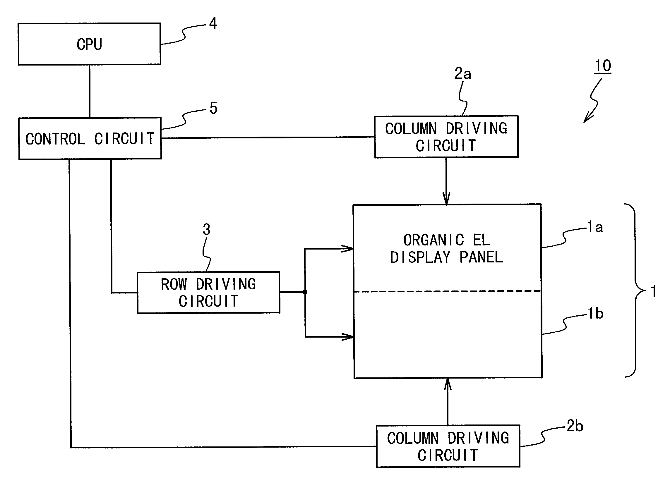
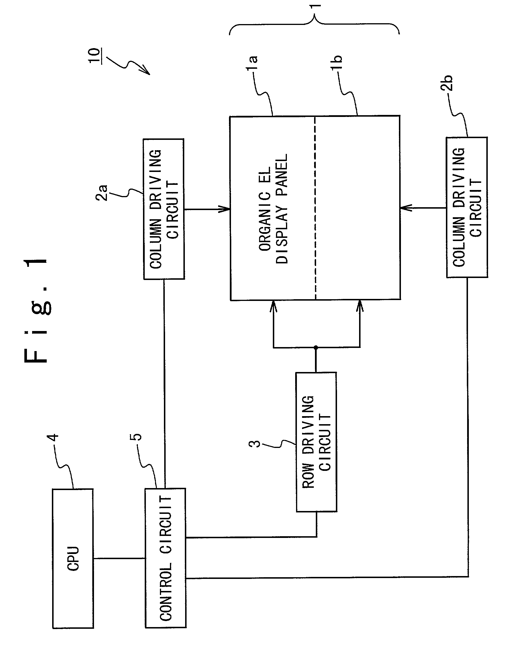
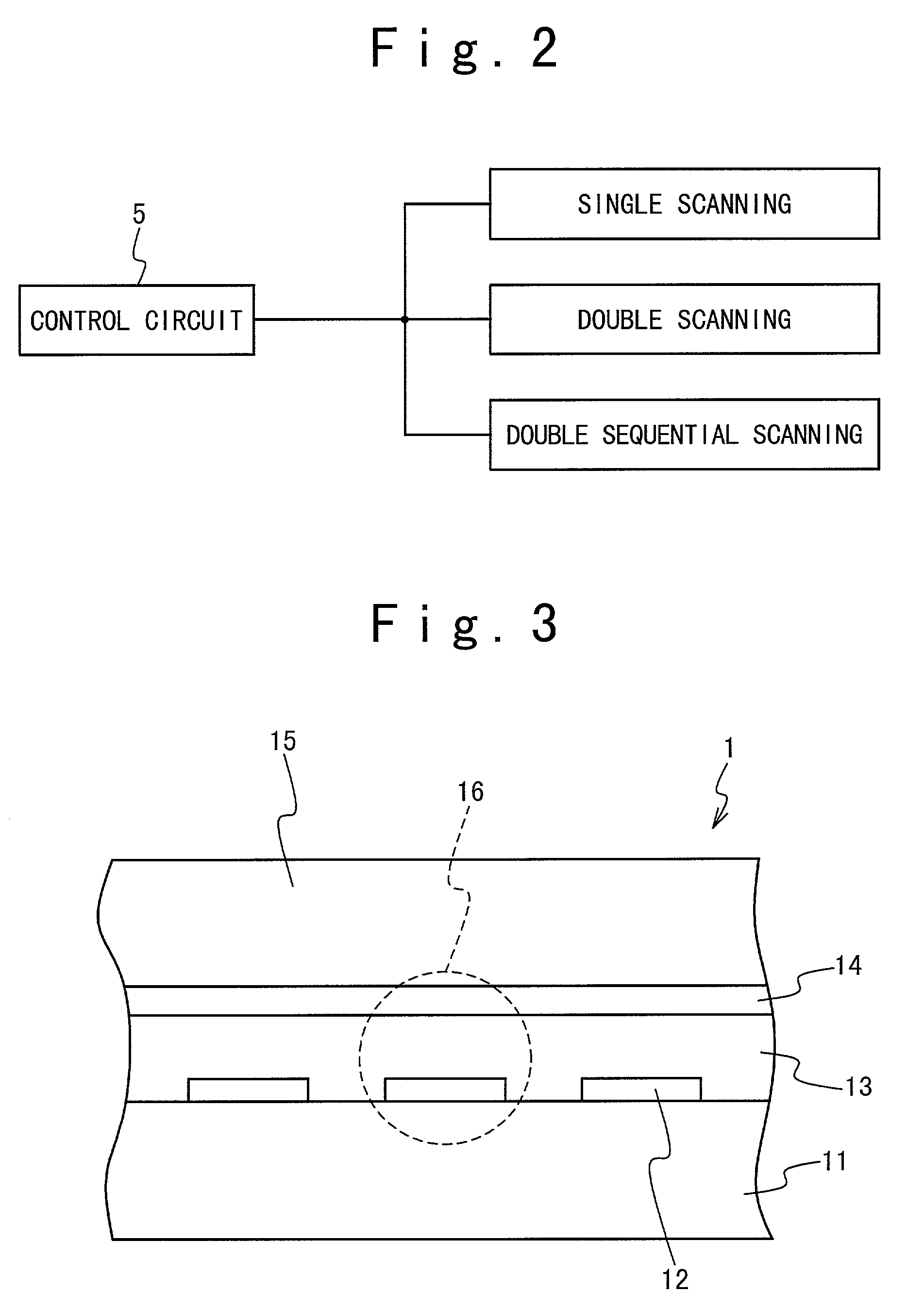
[0041]The image display apparatus such as a color organic EL display apparatus in a mobile phone according to the first embodiment of the present invention will be described with reference to FIG. 1. The image display apparatus of the present invention can change the brightness of display and the power consumption. The image display apparatus in the first embodiment has three operation modes of a single scan mode, a double scan mode, and a double sequential scan mode, as shown in FIG. 2. By switching those modes appropriately, the brightness of the display and the power consumption are changed.

[0042]FIG. 1 is a block diagram showing the color organic EL display apparatus as the image display apparatus with a simple matrix driving system in the first embodiment. As shown in FIG. 1, the color organic EL display apparatus 10 is composed of a color organic EL display apparatus panel as an image disp...


PUM


Abstract

An image display apparatus includes an image display section in which a plurality of light emitting elements are arranged in a matrix at intersections of a plurality of scan lines and a plurality of data lines. A control circuit selects one of modes as an operation mode in response to a mode switching signal, and outputs a data signal and a scan control signal based on an image signal to be displayed and the selected mode. A row driving section is connected to the plurality of scan lines to sequentially drive the plurality of scan lines based on the scan control signal in a unit determined based on the operation mode. A column driving section is connected to the plurality of data lines to sequentially drive the plurality of data lines based on the data signal. In this way, an image corresponding to the image signal is displayed on the image display section.

Description

BACKGROUND OF THE INVENTION[0001]1. Field of the Invention[0002]The present invention relates to an image display apparatus and a method of driving the same.[0003]2. Description of the Related Art[0004]The demand of display apparatuses remarkably increases in recent years. Especially, flat-panel display apparatuses such as a liquid crystal display apparatus (LCD) or a plasma display apparatus (PD) are greatly expected. As one of the flat-panel display apparatuses, a light emitting type image display apparatus such as an electroluminescence (EL) display apparatus has a high visibility and is superior in a view angle. The light emitting type image display apparatus does not need a backlight, unlike the LCD apparatus. Also, attention is paid to an organic electroluminescence image display apparatus as a plane type display apparatus excellent in response characteristics.[0005]As a driving system of a dot matrix type display apparatus using light emitting elements, there are a simple mat...

Claims


Application Information

Patent Timeline
Patent Type & Authority Patents(United States)
IPC IPC(8): G09G5/00H01L51/50G03B1/00G09G3/20G09G3/22G09G3/30G09G3/32
CPCG03B1/00G09G3/3216G09G2360/144G09G2310/0283G09G2330/02G09G2310/0205G09G3/30
Inventor KOTA, ATSUSHIKAWASHIMA, SHINGONISHIGAKI, EITARO
Owner SAMSUNG DISPLAY CO LTD
Learn More