
Coating device

Active Publication Date: 2007-02-13
BAND ZINK
View PDF13 Cites 13 Cited by
  • Summary
  • Abstract
  • Description
  • Claims
  • Application Information

AI Technical Summary

Benefits of technology

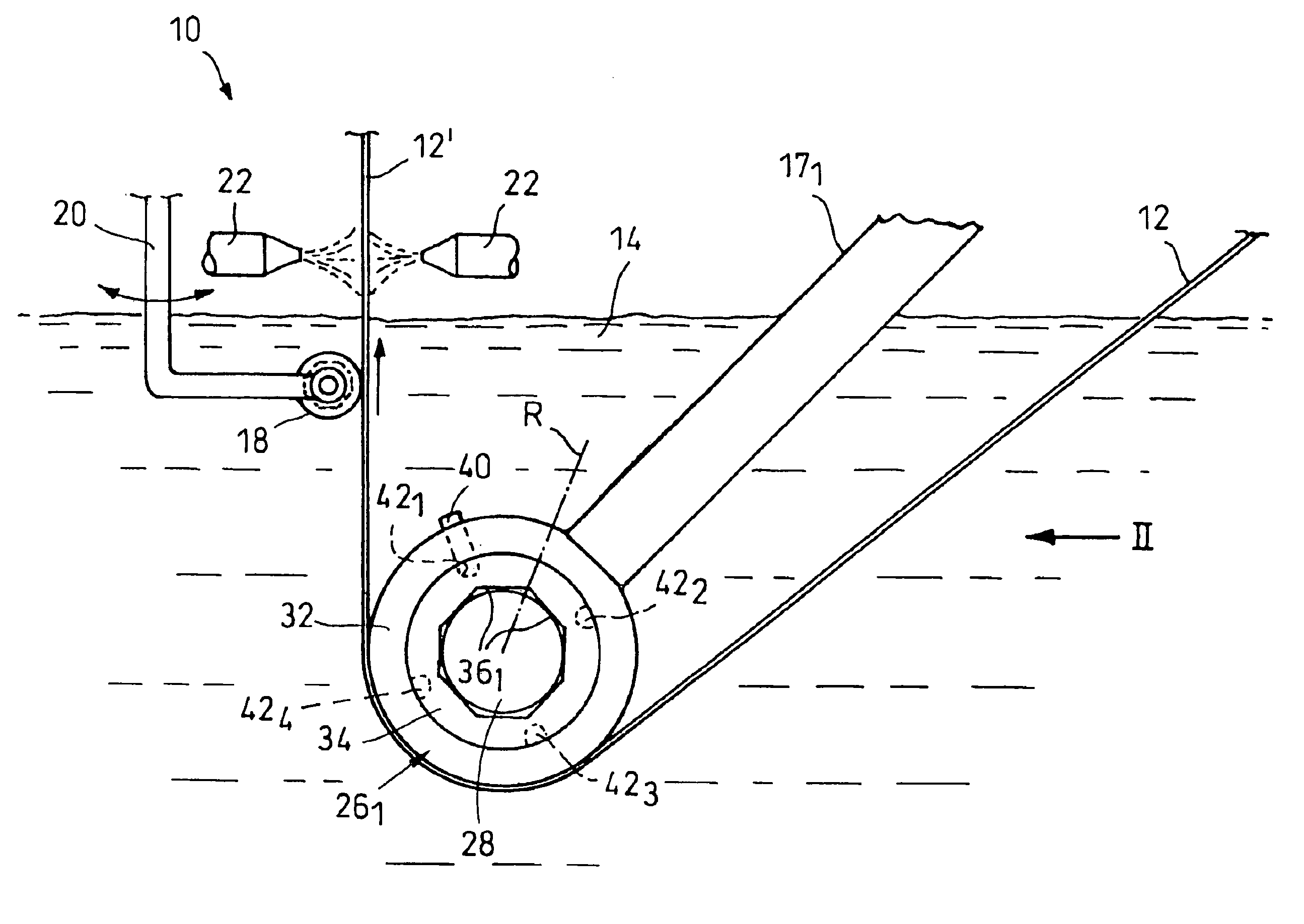
[0004]In the coating device according to the invention, the bearing bush is configured so as to be closed in circumferential direction and comprises at least three bearing surfaces forming several pairs of bearing surfaces. In circumferential direction, the bearing bush in the bearing housing is adapted to be rotated and set in several rotational positions. For locking the bearing bush in the set rotational position, a releasable bearing bush fixing element is provided. Now, each slide bearing comprises at least three bearing surfaces forming at least two different pairs of bearing surfaces with each other. The bearing bush is arranged so as to be rotated and fixed in the bearing housing so that, after one pair of bearing surfaces is worn, the bearing bush can be twisted so far that another partially or completely non-worn pair of bearing surfaces can be used. After one pair of bearing surfaces is worn, an exchange of the entire bearing bush is thus avoided once or several times. Thereby, the service life of a bearing bush, i.e., the time interval between a complete exchange and the next complete exchange of the bearing bush is considerably extended. It only takes a short time to replace a worn pair of bearing surfaces by a non-worn pair of bearing surfaces of the same bearing bush. This reduces the maintenance costs and extends the operation times of the coating installation.
[0005]The configuration of the bearing bush, which is completely closed circumferentially, further largely avoids the expansion of the two bearing surface which is unavoidable in non-closed bearing bushs at high radial loads. This, in turn, reduces the risk of fracture in the zone between the two bearing surfaces to a minimum. This means that by the closed configuration, the bearing bush is stabilized against the expansion forces caused by the shafts at high radial loads and a fracture is avoided.
[0007]According to a preferred embodiment, the bearing bush's outside comprises at least two fixing grooves into which the fixing element is insertable to lock the bearing bush. The fixing element can be configured in the form of a feather key and establishes the positive connection between the bearing housing and the bearing bush in circumferential direction. For setting a new non-worn pair of bearing surfaces, the fixing element is withdrawn from the first fixing groove, the bearing bush is twisted such that a non-worn pair of bearing surfaces is in its working position, and the fixing element is now inserted into the second fixing groove arranged correspondingly to fix the bearing bush in this rotational position. Thus, an ability of the bearing bush of being rotated and reliably fixed is realized with simple means.

Problems solved by technology

Because of the occurring great radial forces, the high melt temperature and the possibly high chemical aggressiveness of the metal melt, the slide bearings are subject to heavy wear.
In a continuously operating coating installation, the slide bearings are worn so heavily even after a few days that they have to be replaced.
Thus, several hours are required to exchange the two bearings, which is a great cost factor.

Method used


Image

  • Coating device
  • Coating device
  • Coating device

Examples


Embodiment Construction

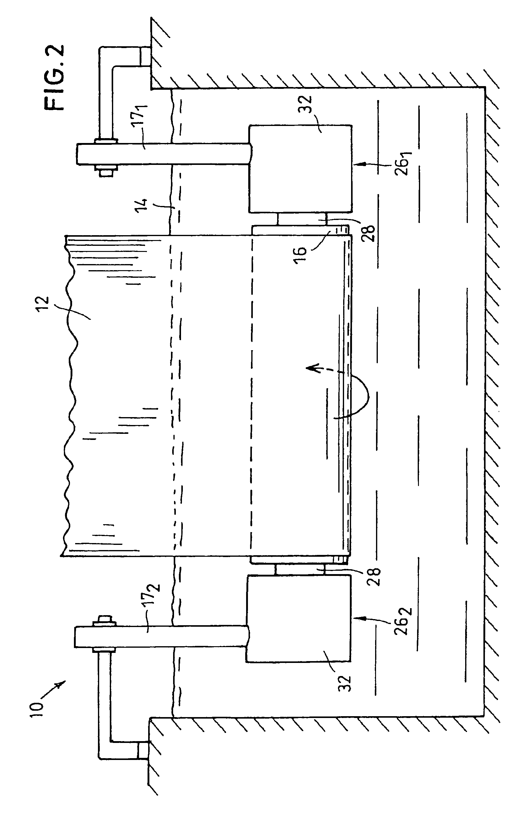
[0017]In FIG. 1, a side view of a coating device 10 is illustrated in a simplified manner. A metal strip 12 is led through a metal melt 14 to provide the surface of the metal strip 12 with a thin metal coating. The metal melt may consist of liquid zinc, lead, tin, aluminum, galvalum, galfan or other metals suitable for coating metal. Depending on the type of the molten metal, the metal melt 14 has a temperature of 400–1000° C.

[0018]The metal strip 12 is introduced into the molten metal 14 at an angle of 30–45° to the horizontal line and deviated upwards in the melt 14 by a rotatable deviating shaft 16 so that the metal strip 12′ is led vertically upwards out of the metal melt 14 again. The angle of wrap of the metal strip 12,12′ around the deviating shaft 16 amounts to approximately 130°. The tensile force of the metal strip 12 amounts to between 1.0–5.0 tons.

[0019]For stabilizing the metal strip 12,12′ , a stabilizing shaft 18 abuts on the metal strip 12′ moving vertically out of t...


PUM

PropertyMeasurementUnit
Forceaaaaaaaaaa
Circumferenceaaaaaaaaaa

Abstract

A coating device (10) for coating a metal strip (12) in a metal melt (14) includes a shaft (16,18) that is rotatable in the metal melt (14) for guiding the metal strip (12), and a slide bearing (261, 262) for supporting the shaft (16,18). The slide bearing (261, 262) is formed by a bearing housing (32) and a bearing bushing (34) that has several pairs (361–364) of bearing surfaces and is configured so as to be circumferentially closed. The bearing bushing (34) is adapted to be set in selected rotational positions in circumferential direction in the bearing housing (32). A releasable bearing bushing fixing element (40) locks the bushing in each of the selected rotational positions with respect to the bearing housing (32). Thereby, a worn pair (361–364) of bearing surfaces can be simply replaced by a non-worn pair (361–364) of bearing surfaces by a rotation of the bearing bushing.

Description

BACKGROUND OF THE INVENTION[0001]The invention relates to a coating device for coating a metal strip in a melt of a metal.[0002]Coating devices are used for coating metal strips and sheet metals with zinc, aluminum, tin, lead, galvalum or galfan. In doing so, the metal strip or sheet metal is drawn through a metal melt of the coating metal which is several hundred degrees hot: the metal strip is continuously immersed downward into the metal melt, is deviated upward by a rotating deviating shaft in the metal melt, is steadied by a stabilizing shaft and runs upwards out of the metal melt again. The support of the deviating shaft and / or the stabilizing shaft in the melt is effected in open slide bearings which are configured as wearing bearings. Because of the occurring great radial forces, the high melt temperature and the possibly high chemical aggressiveness of the metal melt, the slide bearings are subject to heavy wear. In a continuously operating coating installation, the slide b...

Claims


Application Information

Patent Timeline
IPC IPC(8): B05C19/02B05C3/132C23C2/00F16C23/04F16C25/02F16C33/04
CPCC23C2/00F16C23/04F16C17/246F16C33/043F16C13/02F16C25/02
Inventor PLATZER, WILFRIED
Owner BAND ZINK
Learn More