Dual size stud electrical connector

a technology of electrical connectors and studs, applied in the direction of transformer/coil connectors, electrical apparatus, connections, etc., can solve the problems of affecting the and affecting the integrity of the electrical interface, etc., to achieve the effect of convenient connection of two different size studs

Active Publication Date: 2007-02-13
HUBBELL INC
View PDF17 Cites 21 Cited by
  • Summary
  • Abstract
  • Description
  • Claims
  • Application Information

AI Technical Summary

Benefits of technology

[0018]By forming the electrical connector in this manner, positioning of the clamping component on different sides of the connector facilitates the connection of two different size studs. The position is enabled by the attachment link.

Problems solved by technology

Movement of the attached conductors promote slight amounts of torque which cause the screw on bushing stud to loosen, heat up, and eventually fail.
If failure occurs at the electrical interface of the connector or an internal fault in the transformer, all of these conductors must be removed from their respective attachment points to the stud connector.
The problem of having to disconnect a plurality of conductors for the purpose of removing the connector is still prevalent.
This causes a problem with the secure integrity of the electrical interface because the relationship between the stud and the bore of the connector provides only a single line interface.
The setscrew or compression screw utilized in the slip fit connectors does not offer the degree of elastic range in the joint as a bolt under tension.
Not having a resilient clamping force, or stored mechanical energy in the connection, the electrical interface becomes loose, resulting in increased resistance to the joint, which results in increased temperature rise.
This design illustrates the need for securely mounting a single connector on two different transformer bushing stud sizes, yet the same problem of not providing a resilient clamping force as described above is not provided.
The greater differential of the coefficient of thermal expansion of the aluminum causes such connection to become loose as temperature increases, if it does not have the benefit of stored mechanical energy to offset thermal expansion of the aluminum.
The Tamm electrical connection can accommodate only a single stud size, and therefore, lacks the versatility needed in the present market.
Further, the components of this device are not captive, resulting in the propensity of the installer to drop or lose one or more components, particularly the bolt or nut, during installation.
The hazards of such loose hardware are readily apparent in an electrical enclosure.

Method used


Image

  • Dual size stud electrical connector
  • Dual size stud electrical connector
  • Dual size stud electrical connector

Examples


Embodiment Construction

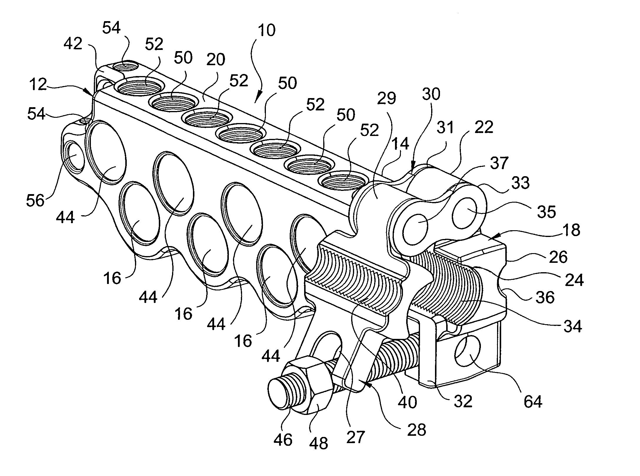
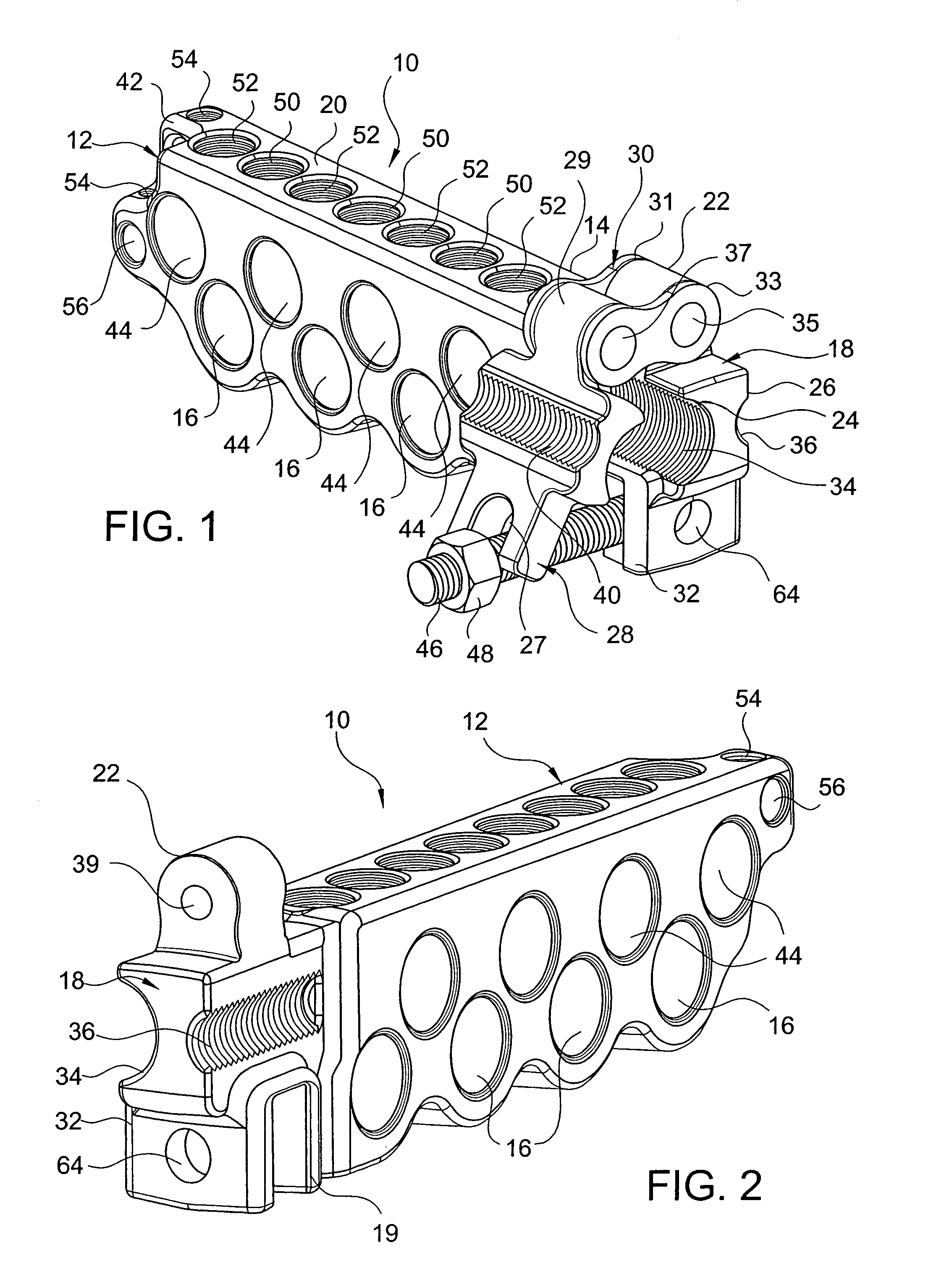
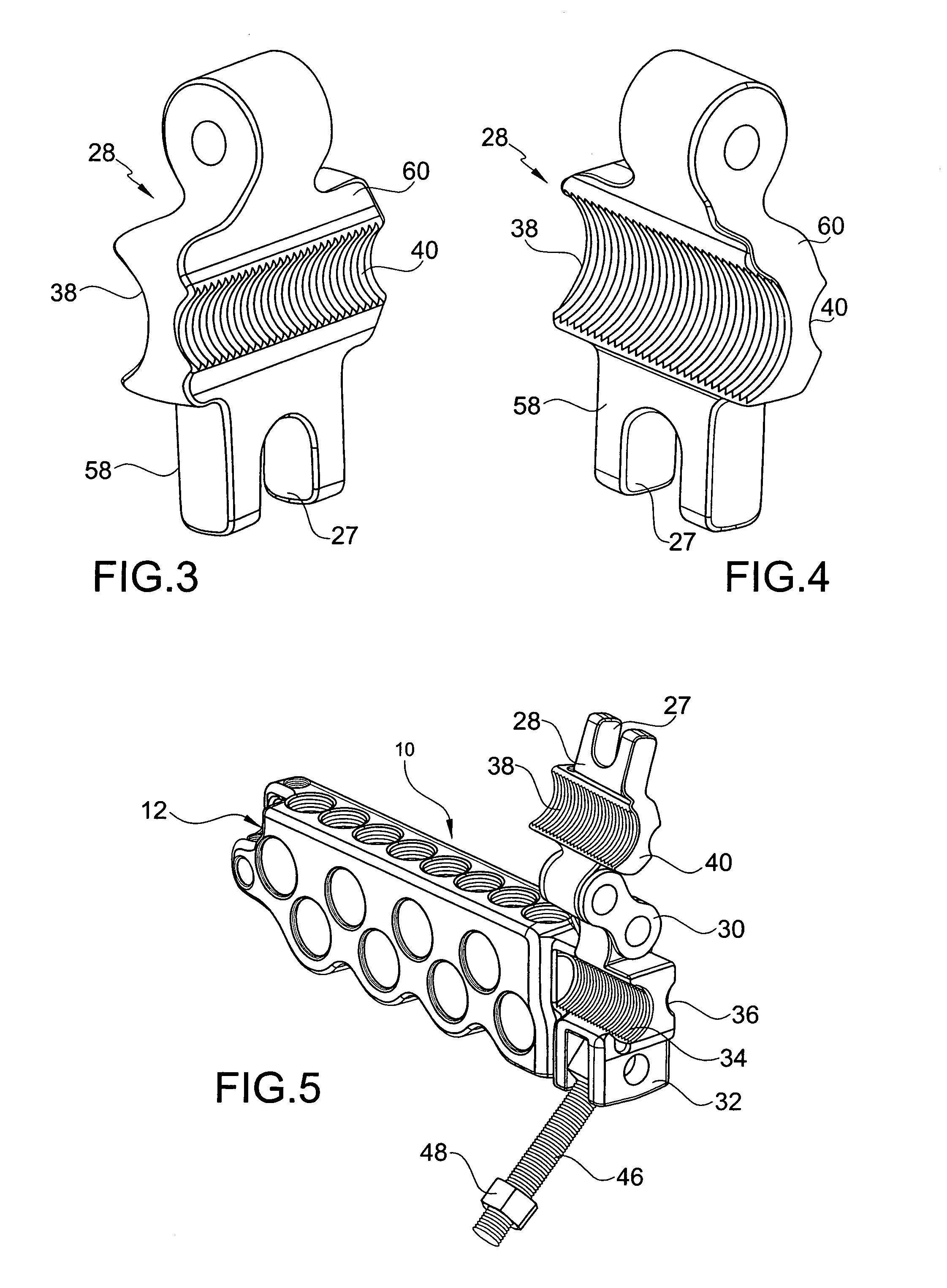
[0030]As seen in FIGS. 1, 7, and 8, an electrical connector 10 links the stud terminal 65 of electrical equipment 66 to multiple branch-circuit wires 62. Electrical connector 10 comprises a transformer bar 12, a connector body 18, and a clamping component 28. The transformer bar 12 has a plurality of conductor bores 16, 44 therein, a distal end 14, and a bar top 20. Connector body 18 is at said distal end 14, and has a boss 22 at the bar top 20 and first and second connector sides 24, 26. Clamping component 28 is pivotally mounted by an attachment link 30 to be selective located adjacent one of said first and second connector sides 24, 26. Referring to FIG. 1, the device is illustrated in its partially closed position, about to be mounted on a larger sized stud, such as a 1–14 UNS stud. Other threaded studs can be used, such as a smaller stud, particularly a ⅝–11 UNC stud.

[0031]The elongated portion of the electrical connector 10 comprises a transformer bar 12. The transformer bar 1...


PUM


Abstract

An electrical connector for clamping securely onto a threaded shaft, comprising a transformer bar, a connector body and a clamping component. The transformer bar has a plurality of conductor bores therein, a distal end, a bar top. The connector body is at the distal end and has a boss at the bar top and first and second clamping sides. The clamping component is pivotally mounted by an attachment link to be selectively located adjacent one of the first and second clamping sides.

Description

FIELD OF THE INVENTION[0001]The present invention relates to an electrical connector designed to clamp securely onto a shaft, typical of a transformer bushing stud. More particularly, the invention relates to an electrical connector comprising a transformer bar, a connector body, and a clamping component designed to fit two common sizes of threaded transformer bushing studs.BACKGROUND OF THE INVENTION[0002]Conventional electrical connectors are known for connecting the studs of transformers to wires. A transformer includes an output conductor in the form of a threaded stud connected to a plurality of individual electrical conductors by a transformer stud connector. The most common methods employed for the application of making electrical connections to transformer bushing studs include: (a) screw on, (b) split screw on, (c) slip fit, (d) modified slip fit providing a saddle or nest for the threaded stud, (e) modified slip fit to accommodate two stud sizes, and (f) clamp on. All of t...

Claims


Application Information

Patent Timeline
Patent Type & Authority Patents(United States)
IPC IPC(8): H01R11/09
CPCH01R4/40H01R11/07H01R4/36Y10S439/907H01R2201/22
Inventor TAMM, CARL R.HAY, ROBERT G.
Owner HUBBELL INC
Why Eureka
Try Eureka