
Lighting and ventilating apparatus and method

a technology of ventilating apparatus and light fixture, which is applied in the direction of lighting and heating apparatus, fixed installation, heating type, etc., can solve the problems of unsatisfactory cooling of light fixture, complicated design, and unaesthetic appearan

Active Publication Date: 2007-02-13
BROAN NUTONE
View PDF20 Cites 155 Cited by
  • Summary
  • Abstract
  • Description
  • Claims
  • Application Information

AI Technical Summary

Benefits of technology

The present invention provides a combination lighting and ventilating apparatus for installation in a structure having a surface. The apparatus includes a main housing with a ventilating inlet and a lighting outlet, a lamp housing recessed within the main housing, a lamp positioned within the lamp housing and recessed with respect to the mounting surface, and a fan positioned to draw air into and through the lamp housing. The apparatus can be installed in a room by positioning the lamp housing within the main housing and the lamp within the lamp housing. The fan can then be driven to move air from the room into the main housing and vent the air from the main housing to a position outside of the room. The technical effects of the invention include efficient ventilation and lighting in a compact space, as well as improved air quality and reduced energy consumption.

Problems solved by technology

Other existing lighting and ventilating units combine elements of a conventional room ventilating fan with a light fixture, but have a bulky, unaesthetic appearance, employ a complicated design, do not adequately cool the light fixture, and / or employ a design in which the components of the unit are inefficiently arranged.

Method used


Image

  • Lighting and ventilating apparatus and method
  • Lighting and ventilating apparatus and method
  • Lighting and ventilating apparatus and method

Examples


Embodiment Construction

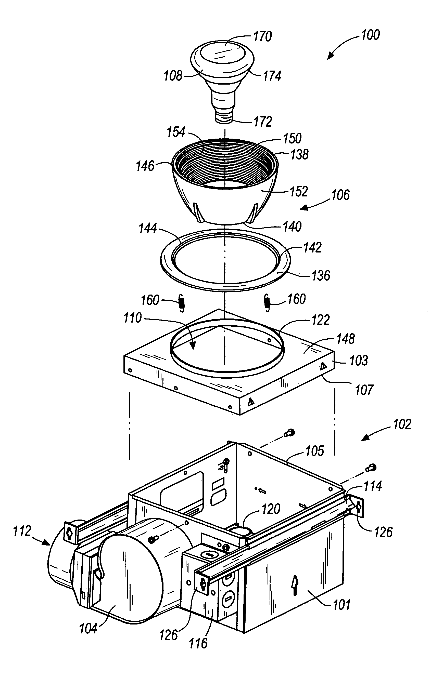
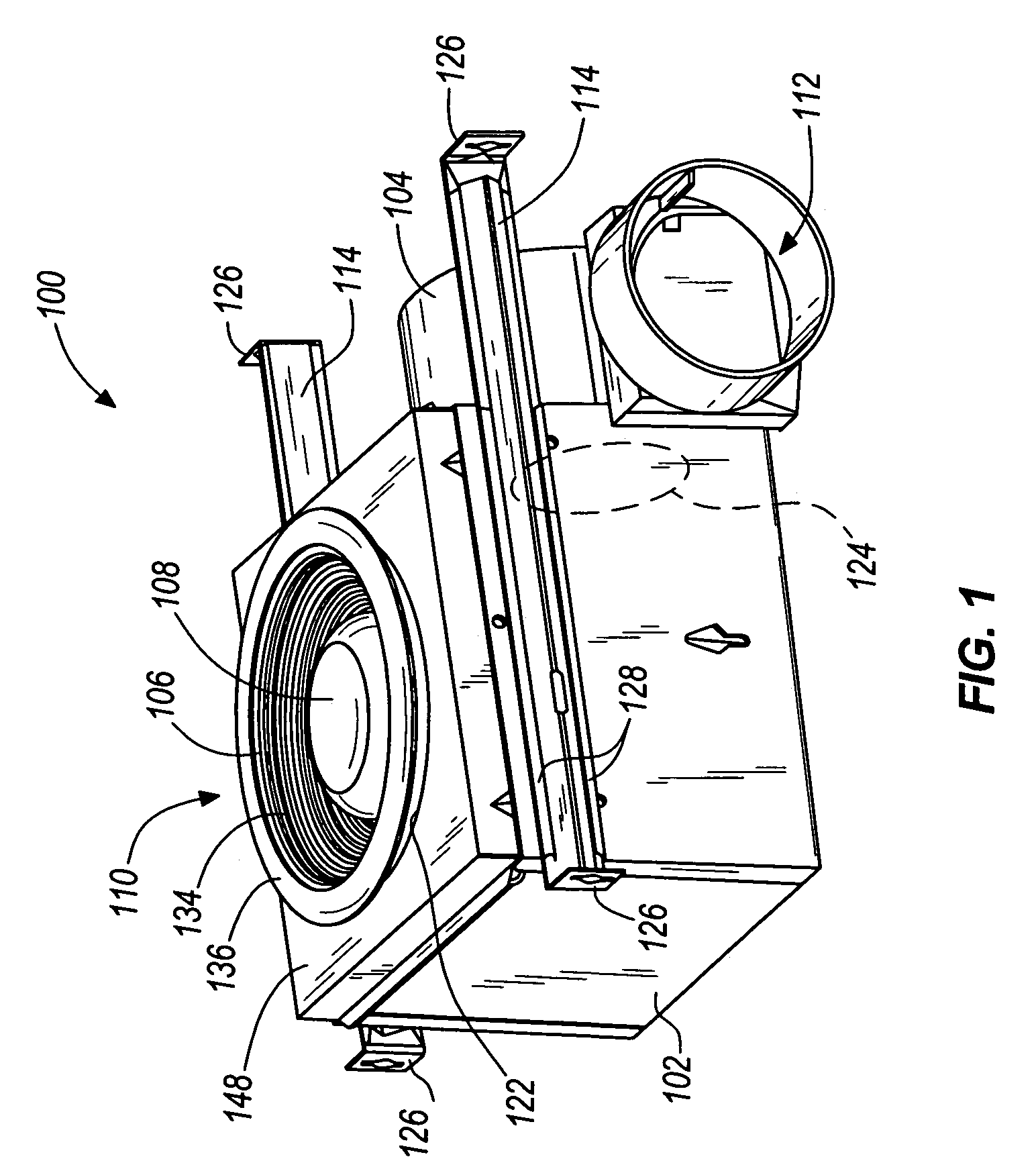
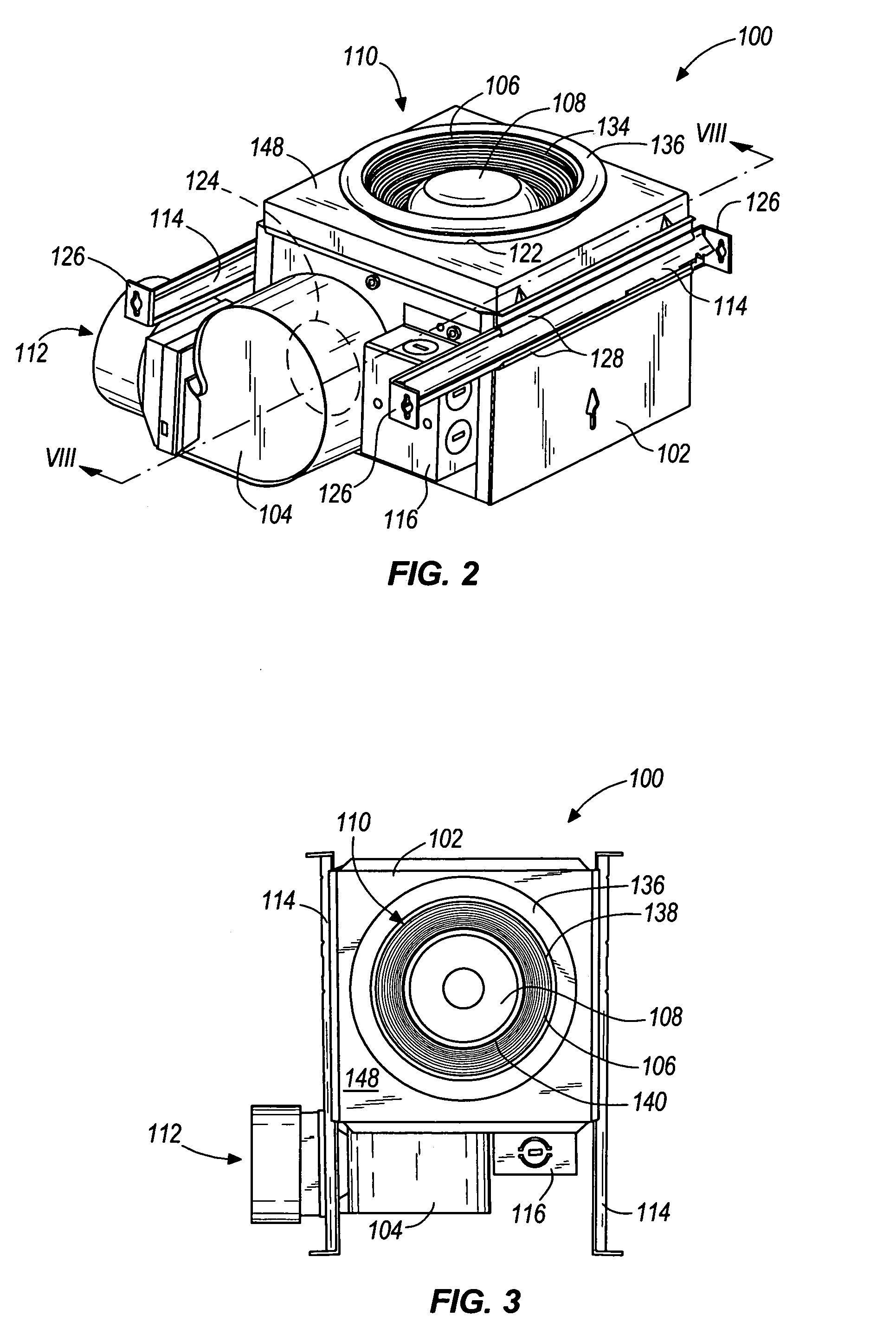
[0022]Referring to the figures, and more particularly to FIGS. 1 and 2, a lighting and ventilating apparatus constructed in accordance with an exemplary embodiment of the present invention is shown generally at 100. The lighting and ventilating apparatus 100 comprises several components and devices which perform various functions. In some embodiments of the present invention, the lighting and ventilating apparatus 100 includes a main housing 102 for housing various components of the apparatus 100, a fan 104 for moving air into and through the apparatus 100 as will be described in greater detail below, a lamp housing 106, a lamp 108, a ventilation inlet 110, a ventilation outlet 112, at least one mounting bracket 114 for mounting the lighting and ventilating apparatus 100 to one or more surfaces or support structures, a junction box 116 for housing one or more electrical connections for the apparatus 100, a motor 118 for driving the fan (not visible in FIGS. 1 and 2), and an electric...


PUM


Abstract

Some embodiments of the present invention provide a combination lighting and ventilating apparatus for installation in a structure. The apparatus can include a main housing having a first aperture that defines a ventilating inlet and a lighting outlet, a lamp housing recessed within the main housing, having first and second apertures spaced a distance from one another, and having a portion that extends outside of the main housing, and a lamp recessed within the lamp housing and the main housing. In some embodiments, the apparatus further includes a fan positioned to draw air into and through the first aperture of the lamp housing, around the lamp, and through the second aperture of the lamp housing. In another aspect of the invention, a method of lighting and ventilating a room using a combination lighting and ventilating apparatus is provided.

Description

BACKGROUND OF THE INVENTION[0001]Some existing lighting and ventilating units are designed for heating a room using radiant heat from a heat lamp, and for ventilating the room using a fan moving air through the unit. In some cases, the fan also functions to carry away heat generated by the heat lamp to avoid overheating other components of the lighting and ventilating unit. In lighting and ventilating units designed for heating a room, the ventilating air can be directed near the lamp in order to draw heat away from the lamp. Other existing lighting and ventilating units combine elements of a conventional room ventilating fan with a light fixture, but have a bulky, unaesthetic appearance, employ a complicated design, do not adequately cool the light fixture, and / or employ a design in which the components of the unit are inefficiently arranged.SUMMARY OF THE INVENTION[0002]Some embodiments of the present invention provide a combination lighting and ventilating apparatus for installat...

Claims


Application Information

Patent Timeline
Patent Type & Authority Patents(United States)
IPC IPC(8): F21V33/00F21V29/02F24F13/078
CPCF21V29/02F21V33/0092F21V29/673F21V29/025F24F13/078F21V29/67
Inventor CRAW, GARY J.KARST, DANIEL L.
Owner BROAN NUTONE
Learn More