
Compound vibration damper assembly

a vibration damper and assembly technology, applied in the field of vibration dampers, can solve the problems of unfavorable damage to computers, measuring devices, and/or control devices, and conventional vibration protection measures that only have limited effect in actual use, and achieve good vibration damping effects

Active Publication Date: 2007-02-13
MITAC TECH CORP
View PDF13 Cites 25 Cited by
  • Summary
  • Abstract
  • Description
  • Claims
  • Application Information

AI Technical Summary

Benefits of technology

"The present invention provides a compound vibration damper assembly that includes both vertical and horizontal vibration force damping members to provide good vibration damping effect in all directions. The assembly can effectively absorb and isolate vibration forces transmitted to a target apparatus in all directions. It is suitable for use in industrial locations to provide full vibration protection for the target apparatus. The assembly includes a vertical damping unit and a horizontal damping unit, with the horizontal damping unit including an elastomeric base plate and an elastomeric top plate with a hollow cylindrical member made of rubber material or similar elasticity."

Problems solved by technology

For example, periodic or irregular or casual vibration that often occur in an industrial location very possibly have adverse influences on or even cause undesired damages to the computers, measuring apparatus, and / or control apparatus mounted therein.
However, it is found the conventional vibration protection measures provide only limited effect in actual use because main bodies of the computers, measuring apparatus, and / or control apparatus are not well protected against vibration.
Moreover, it is also often found in actual industrial locations that the screwed joints between the computers, measuring apparatus, and / or control apparatus and their respective locating platforms tend to become loosened under vibration over a long time to adversely affect normal work of the apparatus.
However, all the currently available vibration protections fail to meet this requirement.

Method used


Image

  • Compound vibration damper assembly
  • Compound vibration damper assembly
  • Compound vibration damper assembly

Examples


Embodiment Construction

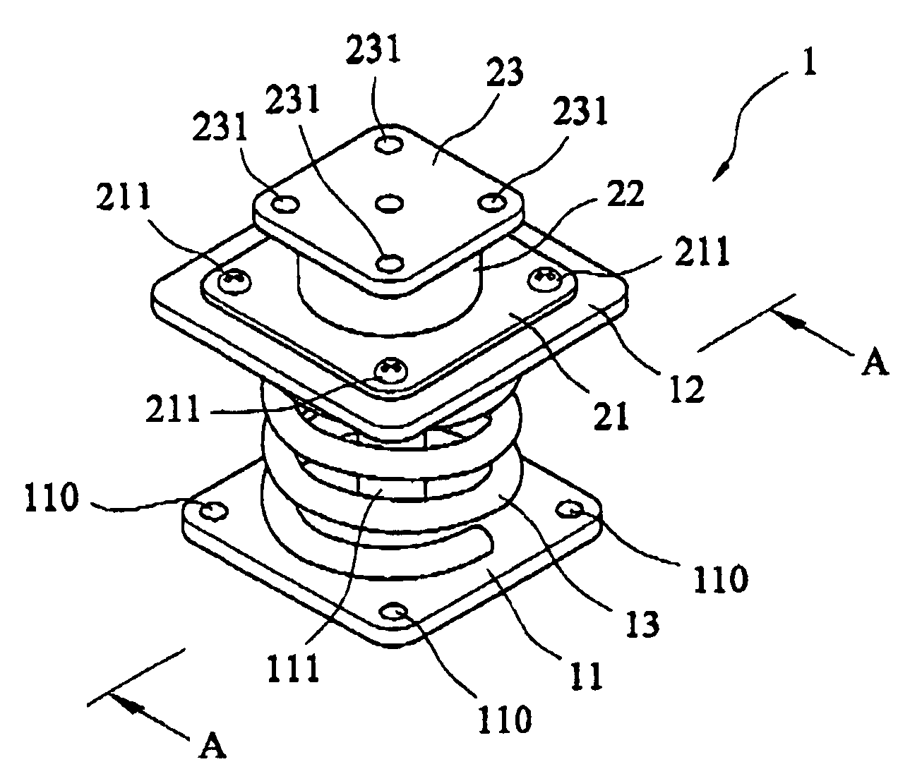
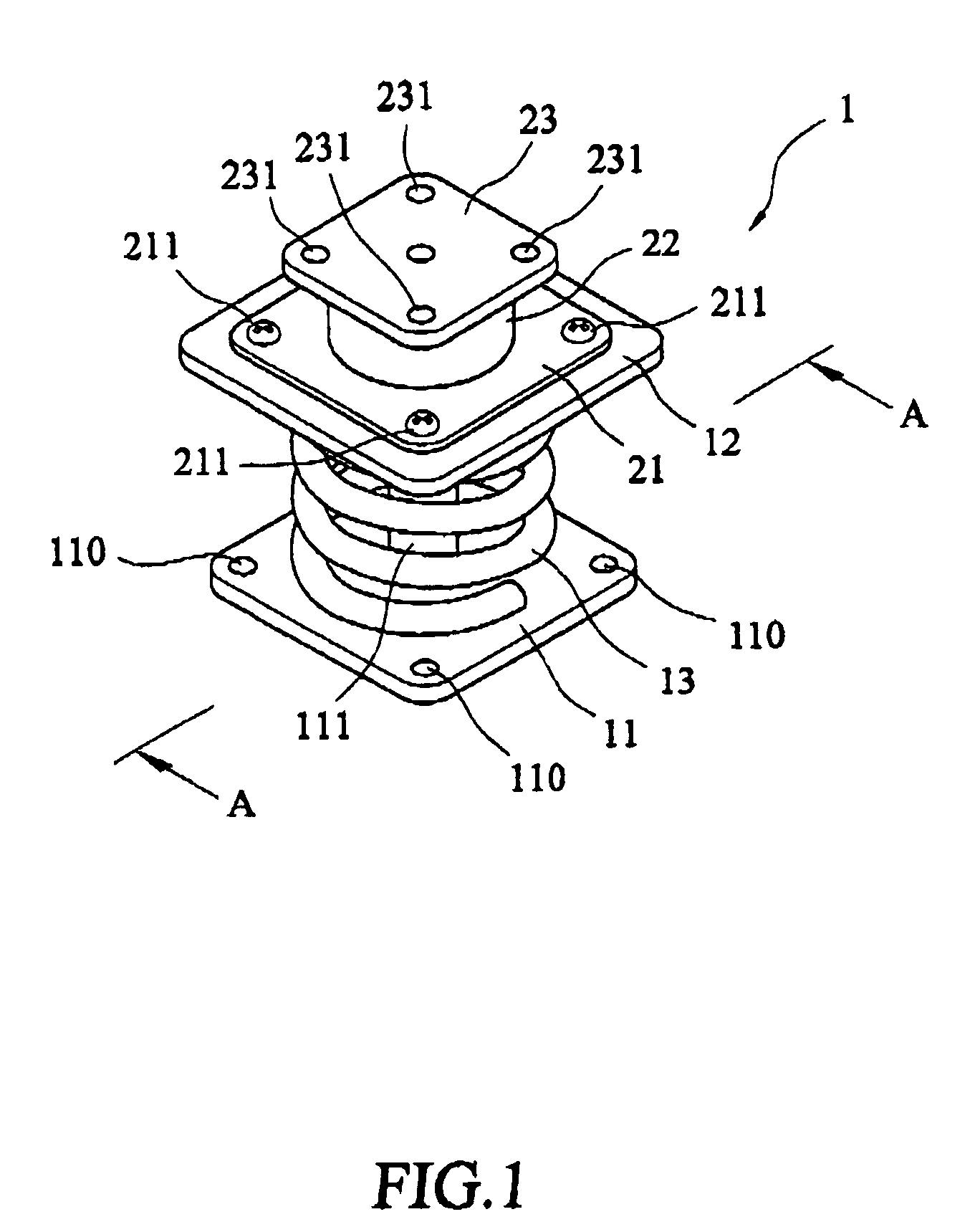
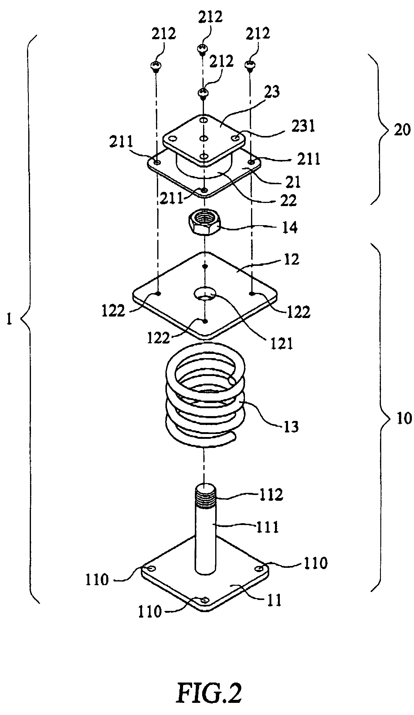
[0022]Please refer to FIGS. 1 and 2 that are assembled and exploded perspective views, respectively, of a compound vibration damper assembly 1 according to a preferred embodiment of the present invention. As shown, the compound vibration damper assembly 1 mainly includes a vertical damping unit 10 and a horizontal damping unit 20. The vertical damping unit 10 is connected at a lower end to a locating surface, which may be, for example, a work platform, a control platform, or an assembling platform in an industrial location, for absorbing a Z-direction vibration force transmitted to a target apparatus, such as an industrial computer, a measuring apparatus, or a control apparatus. The horizontal damping unit 20 is connected to an upper end of the vertical damping unit 10, and has a flat top adapted to support the target apparatus, so as to absorb an X-direction or a Y-direction vibration force transmitted to the target apparatus.

[0023]The vertical damping unit 10 includes a locating b...


PUM


Abstract

A compound vibration damper assembly includes a vertical damping unit fixedly connected at a lower end to a locating surface for absorbing a Z-direction vibration force transmitted to a target apparatus, and a horizontal damping unit connected at a lower end to an upper end of the vertical damping unit and at an upper end to a bottom of the target apparatus for absorbing X- or Y-direction vibration force transmitted to the target apparatus. The vertical damping unit includes a locating base, a central column, a supporting plate, and a vertical vibration force damping member disposed between the supporting plate and the locating base; and the horizontal damping unit includes an horizontal vibration force damping member located between an elastomeric base plate and an elastomeric top plate.

Description

BACKGROUND OF THE INVENTION[0001]1. Field of the Invention[0002]The present invention relates to a vibration damper, and more particularly to a compound vibration damper assembly that supports and fixedly connects a target apparatus thereon to a locating surface, and absorbs X-, Y-, and Z-direction vibration forces transmitted to the target apparatus.[0003]2. Description of the Prior Art[0004]It is a common practice to mount computers, measuring apparatus, and / or control apparatus on work platforms, control platforms, and / or assembling platforms in industrial locations, so as to perform necessary industrial procedure control, measurement, calibration, correction, etc. Conventionally, these computers, measuring apparatus, and / or control apparatus are normally directly locked to the work, control, and / or assembling platforms using fastening means.[0005]It is known that industrial locations require much more strict environmental conditions than that required by office or commercial loc...

Claims


Application Information

Patent Timeline
Patent Type & Authority Patents(United States)
IPC IPC(8): F16M13/00F16F3/10F16F15/00F16M5/00F16M11/00
CPCF16F3/10
Inventor CHI, CHING-HSUNG
Owner MITAC TECH CORP
Learn More