
Helical channel fuel distributor and method

a fuel distributor and helical channel technology, applied in the direction of combustion process, hot gas positive displacement engine plant, lighting and heating apparatus, etc., can solve the problems of poor spray quality, easy contamination or plugging of holes such as small size, and difficult drilling of identical holes of such a small siz

Active Publication Date: 2007-02-13
PRATT & WHITNEY CANADA CORP
View PDF16 Cites 23 Cited by
  • Summary
  • Abstract
  • Description
  • Claims
  • Application Information

AI Technical Summary

Problems solved by technology

This configuration poses several problems, one of which is the fact that drilling identical holes of such a small size can be very difficult.
If sufficient similarity between metering hole sizes is not achieved, the fuel film is not uniform, causing a poor spray quality.
In addition, holes of such a small size are very susceptible to contamination or plugging.
Another problem with the prior art is that the channels upstream of the metering holes are exposed to a high amount of heat input through adjacent walls due to external heat transfer from hot air to the cool walls.
This can lead to coke formation and hole plugging.
Also, the resistance of the metering holes is often insufficient to reach the desired nozzle resistance value, and a tuning orifice is often required at the inlet of the nozzle to compensate.
This presents a risk in manufacturing since braze can run into the metering holes, blocking them after the braze sets.

Method used


Image

  • Helical channel fuel distributor and method
  • Helical channel fuel distributor and method
  • Helical channel fuel distributor and method

Examples


Embodiment Construction

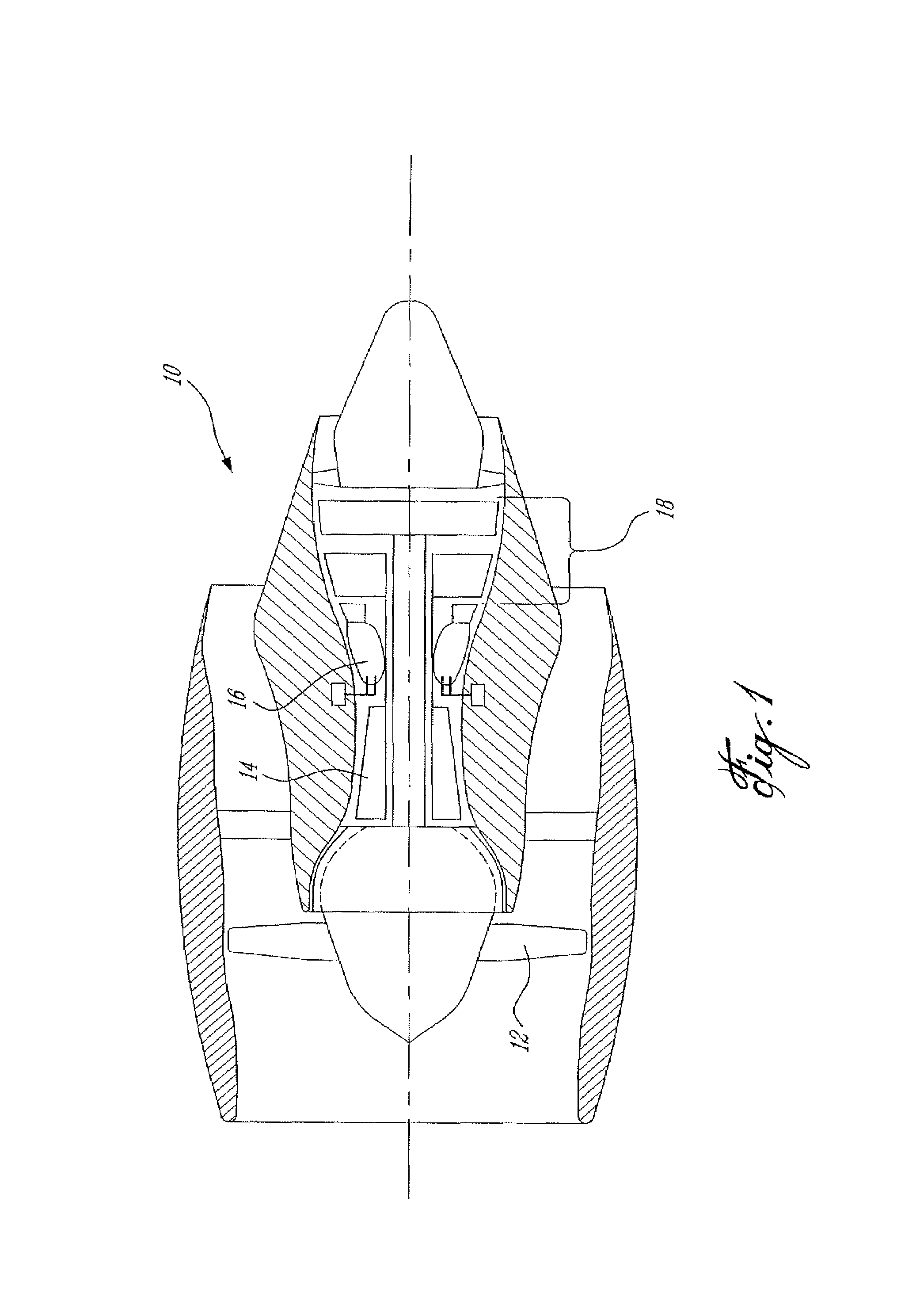
[0022]FIG. 1 illustrates a gas turbine engine 10 of a type preferably provided for use in subsonic flight, generally comprising in serial flow communication a fan 12 through which ambient air is propelled, a multistage compressor 14 for pressurizing the air, a combustor 16 in which the compressed air is mixed with fuel and ignited for generating an annular stream of hot combustion gases, and a turbine 18 for extracting energy from the combustion gases.

[0023]Referring to FIG. 2, the combustor section 16 is shown. The combustor section 16 includes an annular casing 20 and an annular combustor tube 22 concentric with the turbine section 18 and defining a combustor chamber 23. The turbine section 18 is shown with a typical rotor 24 having blades 26 and a stator vane 28 upstream from the blades 26.

[0024]A fuel nozzle 30 is shown as being located at the end of the annular combustor tube 22 and directly axially thereof. The fuel nozzle 30 includes a fitting 32 to be connected to a typical ...


PUM

PropertyMeasurementUnit
lengthaaaaaaaaaa
depthaaaaaaaaaa
flow resistanceaaaaaaaaaa

Abstract

The present invention includes a fuel distributor for a fuel nozzle in a gas turbine engine comprising an inner tubular body and an outer tubular body respectively having an outer body inner surface and an inner body outer surface adapted to be in sealing contact one with the other, at least two helical fuel channels defined in at least one of the inner and outer surfaces and being in fluid communication with a fuel inlet, and a channel exit port for each helical fuel channel. The present invention also includes a method of distributing fuel in a fuel nozzle comprising the steps of providing at least two helical channels in the fuel nozzle, each having a channel exit port, providing a fuel inlet cavity in fluid communication with the helical channels, and flowing fuel in the fuel inlet cavity, the helical channels and the channel exit ports.

Description

BACKGROUND OF THE INVENTION[0001]1. Field of the Invention[0002]The present invention relates to gas turbine engines, and more particularly to a fuel nozzle for such gas turbine engines.[0003]2. Background Art[0004]Fuel nozzles of gas turbine engines usually comprise a fuel distributor for dividing the fuel in several equal streams in order to develop a uniform fuel film. The fuel distributor is often also responsible for swirling the fuel streams to obtain a good fuel spray distribution.[0005]Fuel distributors usually comprise a sealed disk element having a plurality of circumferentially spaced apart small metering holes or slots. The disk is usually mounted on a cylindrical channel adapted to deliver the fuel. The small metering holes are drilled with an axial as well as a circumferential orientation in order to provide a swirl to the fuel passing therethrough.[0006]This configuration poses several problems, one of which is the fact that drilling identical holes of such a small si...

Claims


Application Information

Patent Timeline
Patent Type & Authority Patents(United States)
IPC IPC(8): F23R3/28F23R3/14F23D11/10F23D11/38
CPCF23D11/105F23D11/383F23R3/286F23D2900/11101Y10T29/4932Y10T29/49348F23D2900/14021
Inventor PROCIW, LEV ALEXANDER
Owner PRATT & WHITNEY CANADA CORP
Learn More