Inflatable blanket for use in cardiac surgery
- Summary
- Abstract
- Description
- Claims
- Application Information
AI Technical Summary
Benefits of technology
Problems solved by technology
Method used
Image
Examples
first embodiment
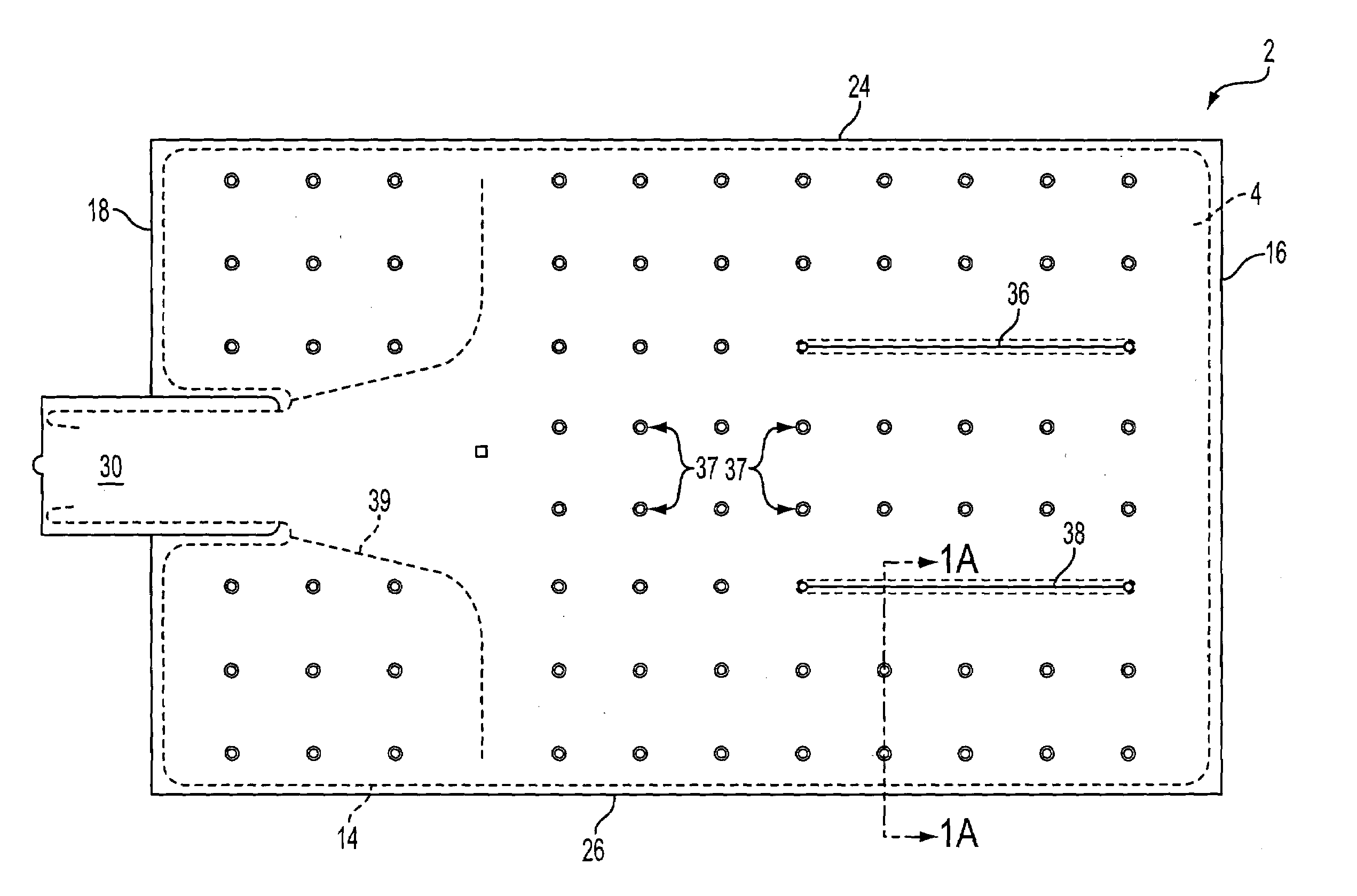
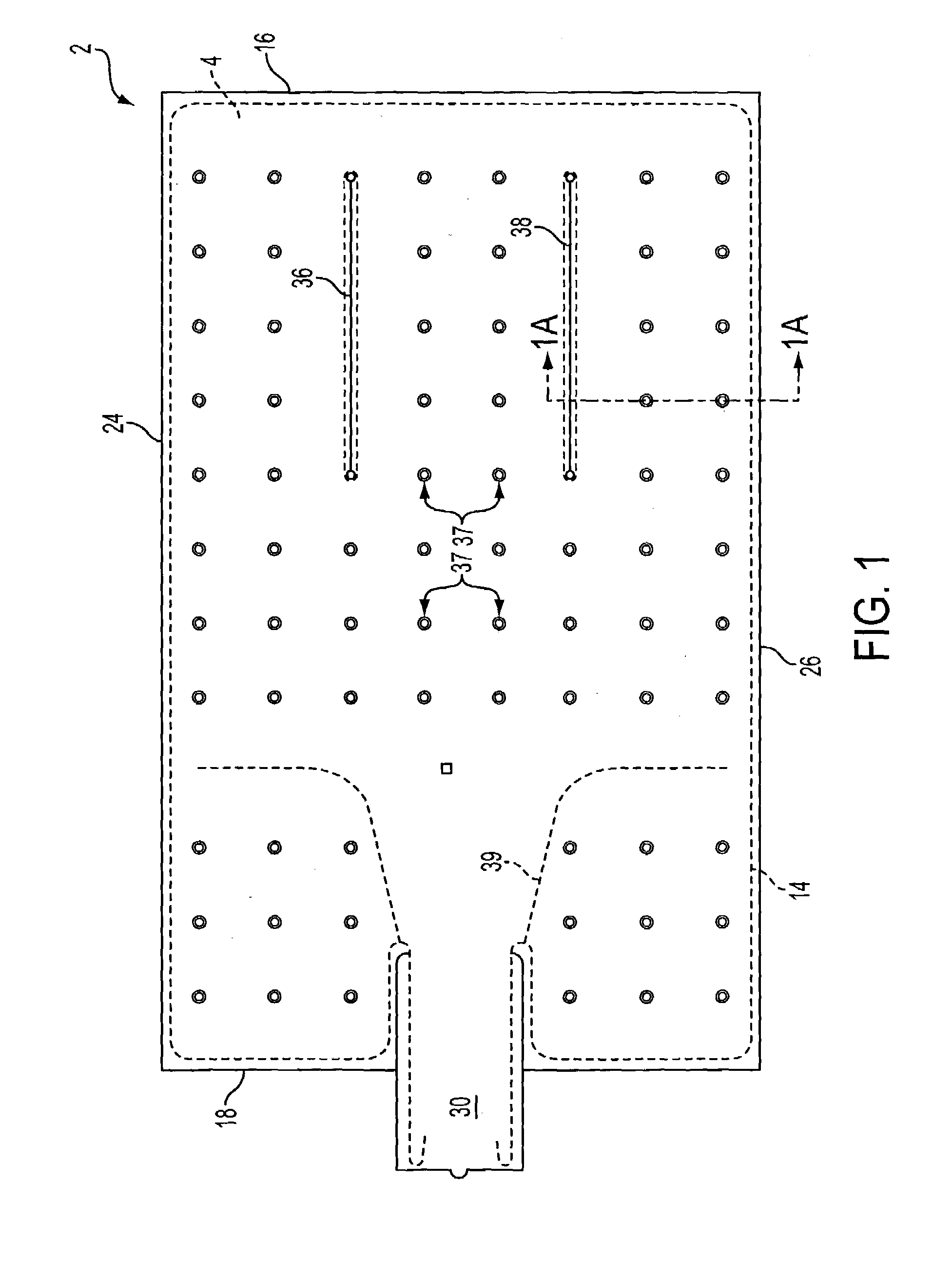
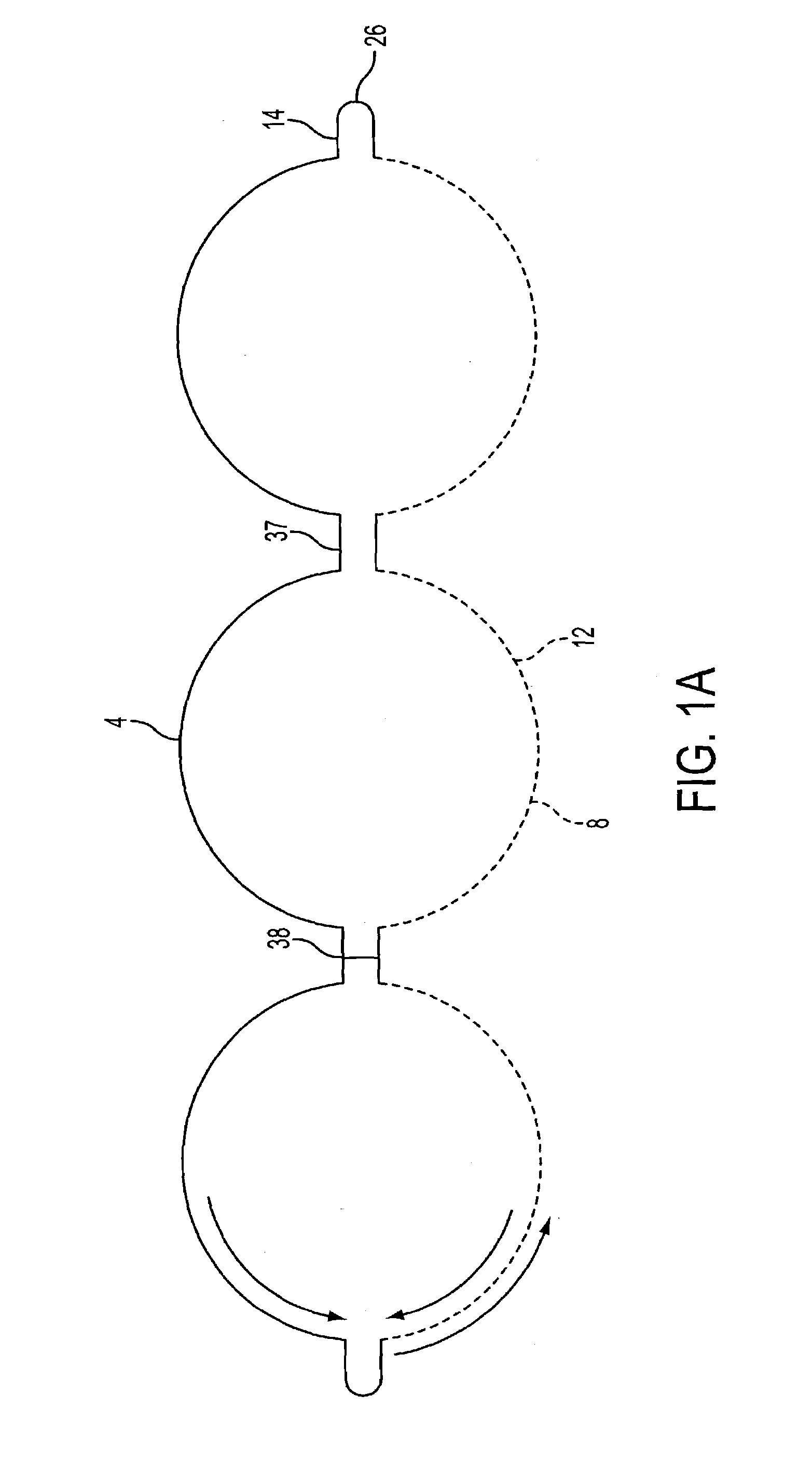
[0024]In FIG. 1 is shown an inflatable blanket 2 for a forced air convection system according to the invention. The inflatable blanket 2 includes an upper sheet 4 and a lower sheet (not shown in FIG. 1). Inflatable blanket 2 may be made of, e.g. a polymer such as a plastic, a fabric, or a composite fiber.
[0025]Inflatable blanket 2 has a generally rectangular shape with an upper end 16, a lower end 18 for positioning near, e.g. feet of a patient when the blanket 2 is in use, and two sides 24, 26 which may be, e.g. substantially parallel, with an inflatable cavity between the upper sheet 4 and the lower sheet.
[0026]The upper sheet 4 and the lower sheet are sealed together around peripheral edges 14 to form the inflatable blanket 2. Peripheral edges 14 may be sealed by, e.g. plastic welding, heat welding, or by applying an adhesive to one or both peripheral edges 14 and matching peripheral edges 14 together. The adhesive may be e.g. a two-part adhesive, such as an epoxy.
[0027]Upper she...
second embodiment
[0031]In FIG. 2 is shown an inflatable blanket 102 for a forced air convection system according to the invention. The inflatable blanket 102 includes an upper sheet 104 of a first material 106 and a lower sheet 108 of second material 110. First and second materials 106, 108 may be, e.g. a polymer such as a plastic, a fabric, or a composite fiber. First and second materials 106, 108 may be the same material, or different materials.
[0032]The upper sheet 104 and lower sheet 108 are sealed together around peripheral edges 114 to form the inflatable blanket 102. Upper and lower sheets 104, 108 may be sealed by, e.g. plastic welding, heat welding, or by applying an adhesive to one or both peripheral edges 114 and matching peripheral edges 114 together. The adhesive may be e.g. a two-part adhesive, such as an epoxy. Upper sheet 104 and lower sheet 108 may also be sealed together along at least two separable seal lines 136, 138 in a substantially similar manner. Separable seal lines 136,.13...
third embodiment
[0037]In inflatable blanket 302 shown in FIG. 4, a hose 344 with a proximate end 346 may connect the inflation port 330 with a distal end 348 located outside a sterile field 350. Hose 344 may be, e.g. an air supply hose or a plastic tube. Sterile field 350 may be, e.g. an area around patient 322 in which an effort has been made to substantially dispose of, remove, or otherwise render harmless bacteria, organisms, viruses, vileness & corruption, or other entities, living or non-living, that may be potentially detrimental to the health or recovery of patient 322.
[0038]Inflatable blanket 302 may be inflated through the distal end 348 so that the sterile field 350 is not compromised by the incoming inflation medium 334. Thus, inflation medium 334 may enter hose 344 at distal end 348 and travel through hose 344 to proximate end 344 without substantially contacting or contaminating sterile field 350. In one embodiment, the distal end may have a nozzle 352. Nozzle 352 may be, e.g. a connec...
PUM
 Abstract
Description
Claims
Application Information
 - R&D
- Intellectual Property
- Life Sciences
- Materials
- Tech Scout
- Unparalleled Data Quality
- Higher Quality Content
- 60% Fewer Hallucinations
Browse by: Latest US Patents, China's latest patents, Technical Efficacy Thesaurus, Application Domain, Technology Topic, Popular Technical Reports.
© 2025 PatSnap. All rights reserved.Legal|Privacy policy|Modern Slavery Act Transparency Statement|Sitemap|About US| Contact US: help@patsnap.com


