
Field bendable line voltage track lighting system

a track lighting and field technology, applied in the direction of lighting and heating apparatus, lighting support devices, coupling device connections, etc., can solve the problem of no options previously presented

Inactive Publication Date: 2007-02-06
TECH LIGHTING
View PDF22 Cites 60 Cited by
  • Summary
  • Abstract
  • Description
  • Claims
  • Application Information

AI Technical Summary

Benefits of technology

"The present invention is a line voltage track lighting system that includes a bendable track and a lighting fixture that can be connected to the track. The track has first and second conductors enclosed by insulative material with slots for access. The lighting fixture has a track connector that surrounds a portion of the track and has contact pins for engagement with the conductor-carrying slots. This invention offers the benefits of both line voltage track lighting and low voltage rail systems, with the flexibility of a line voltage system and the safety standards of a low voltage system."

Problems solved by technology

While there is need for a lighting system that combines the advantages of 120 volt track lighting with the advantages of low voltage rail systems, no options have been previously presented because of the difficulties associated with meeting safety standards, including the National Electrical Code requirements and safety laboratory testing standards.

Method used


Image

  • Field bendable line voltage track lighting system
  • Field bendable line voltage track lighting system
  • Field bendable line voltage track lighting system

Examples


Embodiment Construction

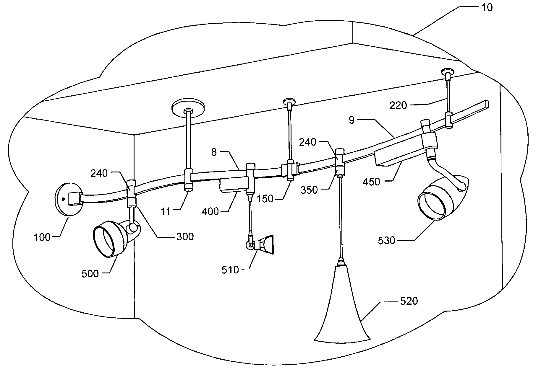
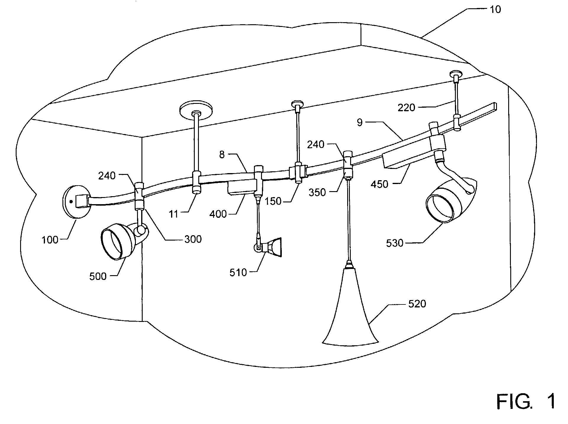
[0027]Referring now to the drawings, FIG. 1 shows a field-bendable line voltage track system 10. Track pieces, for example tracks 8 or 9, can be joined end-to-end using conductive connectors that carry current from one track to the next. Tracks 8 and 9 are fed electrically through one of a variety of power feed options 11 or 100, which allow for ceiling or wall mounted junction boxes. Mechanical supports 220 are offered with the system to suspend tracks 8 and 9 from a ceiling. Lighting elements 500, 510, 520 and 530 are attached to track 8 or 9 using track fixture connectors.

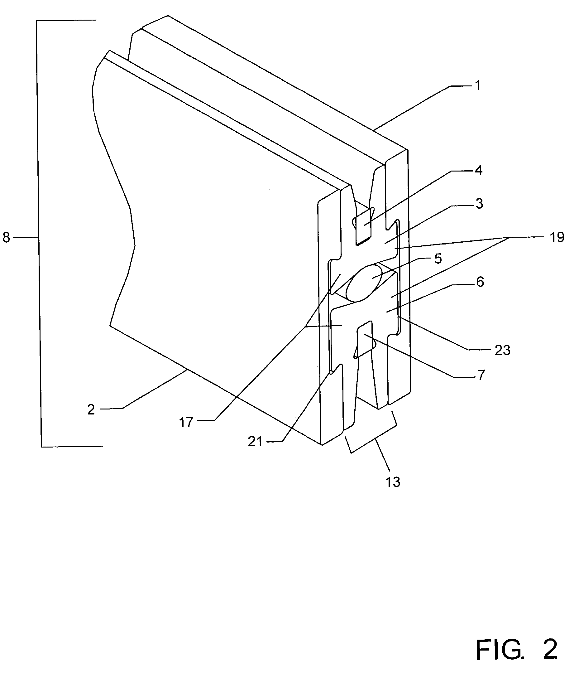
[0028]The system includes a track 8 or 9 that is easily bendable in a lateral direction by hand. Once it has been bent, the track maintains its new shape. Tracks 8 and 9 are identical in their construction. As best shown in FIG. 2, track 8 includes a conductor subassembly 13 and two external sheaths 1 and 2. The conductor subassembly 13 comprises insulators 3 and 6, each having longitudinal slots for receiving c...


PUM


Abstract

A bendable line voltage track lighting system includes a track having a conductor subassembly and first and second bendable sheaths that engage the conductor subassembly. The conductor subassembly includes first and second insulators that receive first and second bus-bars, respectively, and a compression gasket for biasing the two insulators into engagement with guide grooves in the bendable sheaths. Power is fed to the track by power connectors that engage the bus-bars contained within the conductor subassembly. Light fixtures are powered by making electrical contact with the bus-bars of the conductor subassembly.

Description

BACKGROUND OF THE INVENTION[0001]The present invention relates generally to a track lighting system; particularly to a field bendable, line voltage track lighting structure and attachable light fixtures.[0002]Both line voltage track systems and low voltage rail systems are widely used in commercial and residential applications because of the flexibility they offer to the end-user to position and later reposition task lighting. Line voltage track systems employ a track powered at a voltage approximately equal to that of the line voltage of an electrical power line entering an enduser's home, building or other structure. In the United States, this voltage is typically 120 VAC. Low voltage rail systems typically employ a rail powered at a voltage substantially less than line voltage. In the United States, low voltage rail systems typically operate between 12 and 24 VAC. Line voltage track systems have the advantage of longer run lengths and greater choice of lamp options. Low voltage r...

Claims


Application Information

Patent Timeline
Patent Type & Authority Patents(United States)
IPC IPC(8): F21V21/005F21V21/35H01R25/14
CPCH01R25/142F21V21/35
Inventor MOBARAK, AARONSMITH, VICTORWATSON, CHRISTOPHERSHULMAN, MICHAELFURLOW, PAULKAY, GREGORYHEPKEMA, WALLACE
Owner TECH LIGHTING
Learn More