
Circuits, systems, and methods implementing approximations for logarithm, inverse logarithm, and reciprocal

a technology of reciprocal and logarithm, applied in the field of digital signal processing circuits, systems and methods implementing logarithm, inverse logarithm, and reciprocal, can solve the problems of increasing device size, complexity, and device cost, and the implementation of relatively costly solutions in the current digital processing system

Active Publication Date: 2007-01-30
TEXAS INSTR INC
View PDF8 Cites 6 Cited by
  • Summary
  • Abstract
  • Description
  • Claims
  • Application Information

AI Technical Summary

Problems solved by technology

By way of further background, note that some contemporary digital processing systems implement relatively costly solutions to signal processing.
Such approaches may cause numerous problems, such as increasing device size, complexity, and consequently, device cost.
Moreover, in some implementations these increases are simply unacceptable, in which case designs in their entirety may have to be discarded or, at a minimum, considerably altered given the overall system specifications.

Method used


Image

  • Circuits, systems, and methods implementing approximations for logarithm, inverse logarithm, and reciprocal
  • Circuits, systems, and methods implementing approximations for logarithm, inverse logarithm, and reciprocal
  • Circuits, systems, and methods implementing approximations for logarithm, inverse logarithm, and reciprocal

Examples


Embodiment Construction

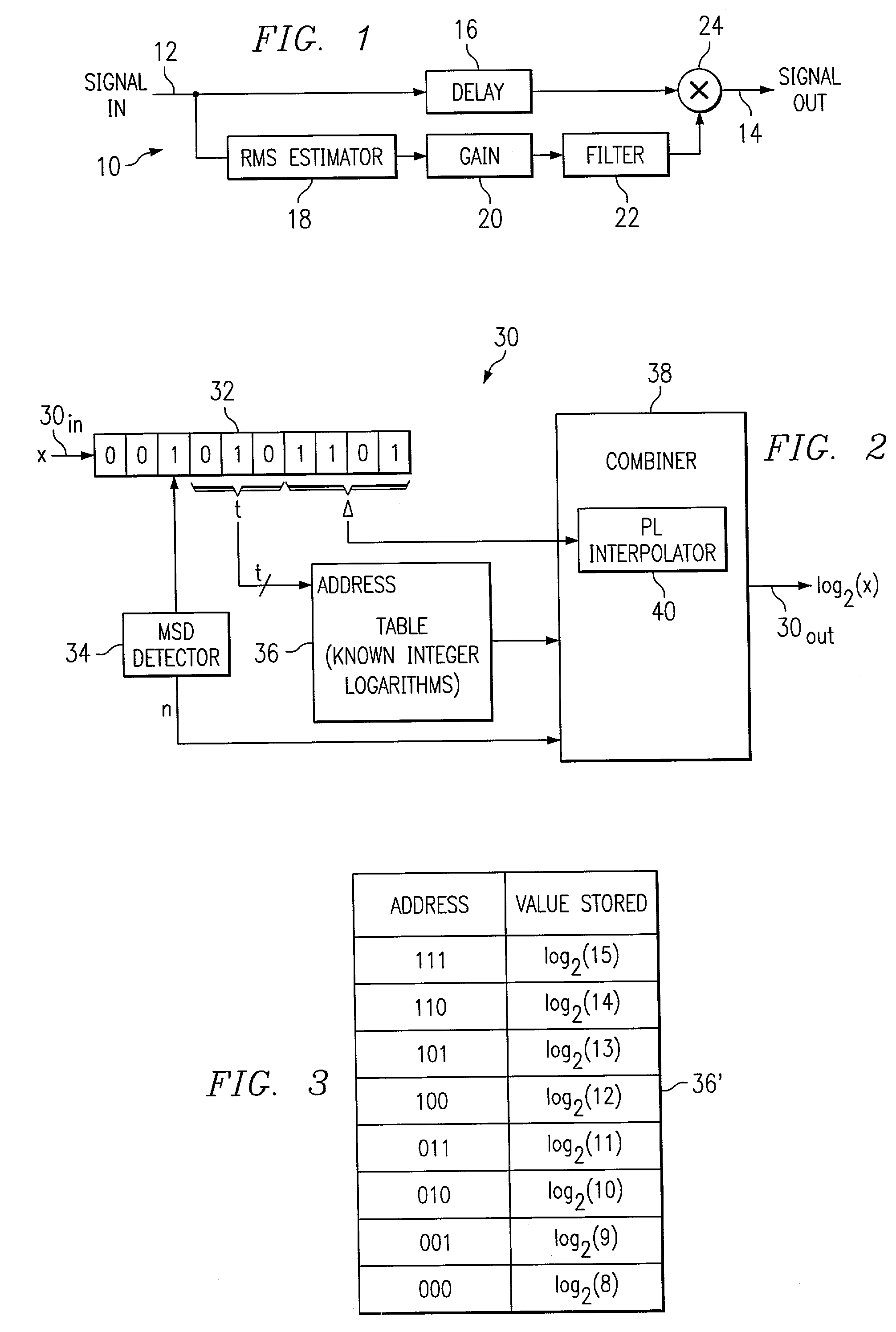
[0020]FIG. 1 illustrates a block diagram of a dynamic range compressor 10 which is shown by way of illustration as a signal processing device in which the preferred embodiments may be implemented, and which is also depicted in the above-incorporated U.S. Pat. No. 6,289,367. Dynamic range compressor 10 receives an audio signal at a signal input 12 and, as demonstrated below, provides an output signal at an output 14 in response to the input signal. Before detailing the relationship of the input and output signals, first consider the signal path between input 12 and output 14, which is as follows. Input 12 is connected to the input of a delay circuit 16, and also to the input of a root mean square (“RMS”) estimator 18. The output of RMS estimator 18 is connected to the input of a gain circuit 20. The output of gain circuit 20 is connected to the input of a filter 22. The output of filter 22 is connected to an input of a combiner 24, which also has an input connected to receive the out...


PUM


Abstract

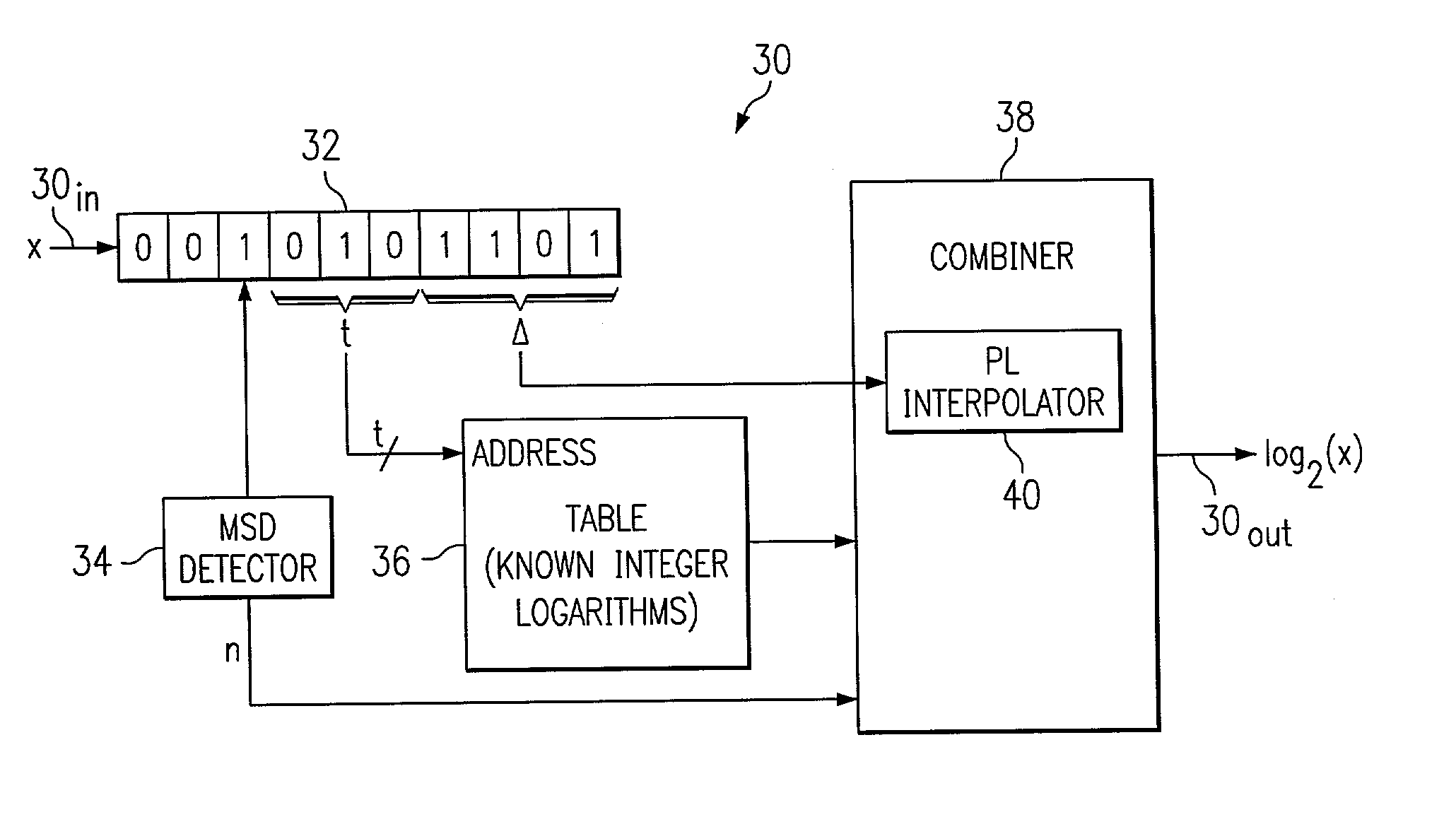
A digital signal system (30) for determining an approximate logarithm of a value of x having a base b is described. The system comprises circuitry for storing x as a digital representation, identifying a most significant digit (MSD) of the digital representation, a table for storing a set of predetermined logarithms having the base b, circuitry for addressing the table in response to a first bit group (t) of the set of bits in respective lesser significant bit locations and for outputting a one of the predetermined logarithms corresponding to a first number (la) in the set of numbers, and circuitry for outputting the approximate logarithm of the value of x in response to the one of the predetermined logarithms and in response to a function estimation between logarithms at a first and second endpoint.

Description

CROSS-REFERENCES TO RELATED APPLICATIONS[0001]This application is related to U.S. patent application Ser. No. 10 / 150,723 entitled “Circuits, Systems, And Methods Implementing Approximations For Inverse Logarithm”, and filed on the same date as the present application and having the same inventor.STATEMENT REGARDING FEDERALLY SPONSORED RESEARCH OR DEVELOPMENT[0002]Not Applicable.BACKGROUND OF THE INVENTION[0003]The present embodiments relate to signal processing and are more particularly directed to digital signal processing circuits, systems, and methods implementing approximations for logarithm, inverse logarithm, and reciprocals.[0004]Digital signal processing is prevalent in numerous types of contemporary technologies, and it involves various types of devices, signals, and evaluations or operations. For example, devices involved in signal processing may include a general purpose digital signal processor (“DSP”), an application specific processor, (“ASP”), an application specific ...

Claims


Application Information

Patent Timeline
IPC IPC(8): G06F1/02G06F1/03G06F7/556G06F1/035
CPCG06F1/0307G06F1/035G06F2101/12
Inventor ALLRED, RUSTIN W.
Owner TEXAS INSTR INC
Learn More