
Reducing noise in audio systems

a technology for reducing noise and audio systems, applied in the field of acoustics, can solve the problems of large difference between summed and subtracted signal powers, and achieve the effect of reducing propagation speed and rapid loss of signal coheren

Active Publication Date: 2007-01-30
MH ACOUSTICS
View PDF11 Cites 194 Cited by
  • Summary
  • Abstract
  • Description
  • Claims
  • Application Information

AI Technical Summary

Benefits of technology

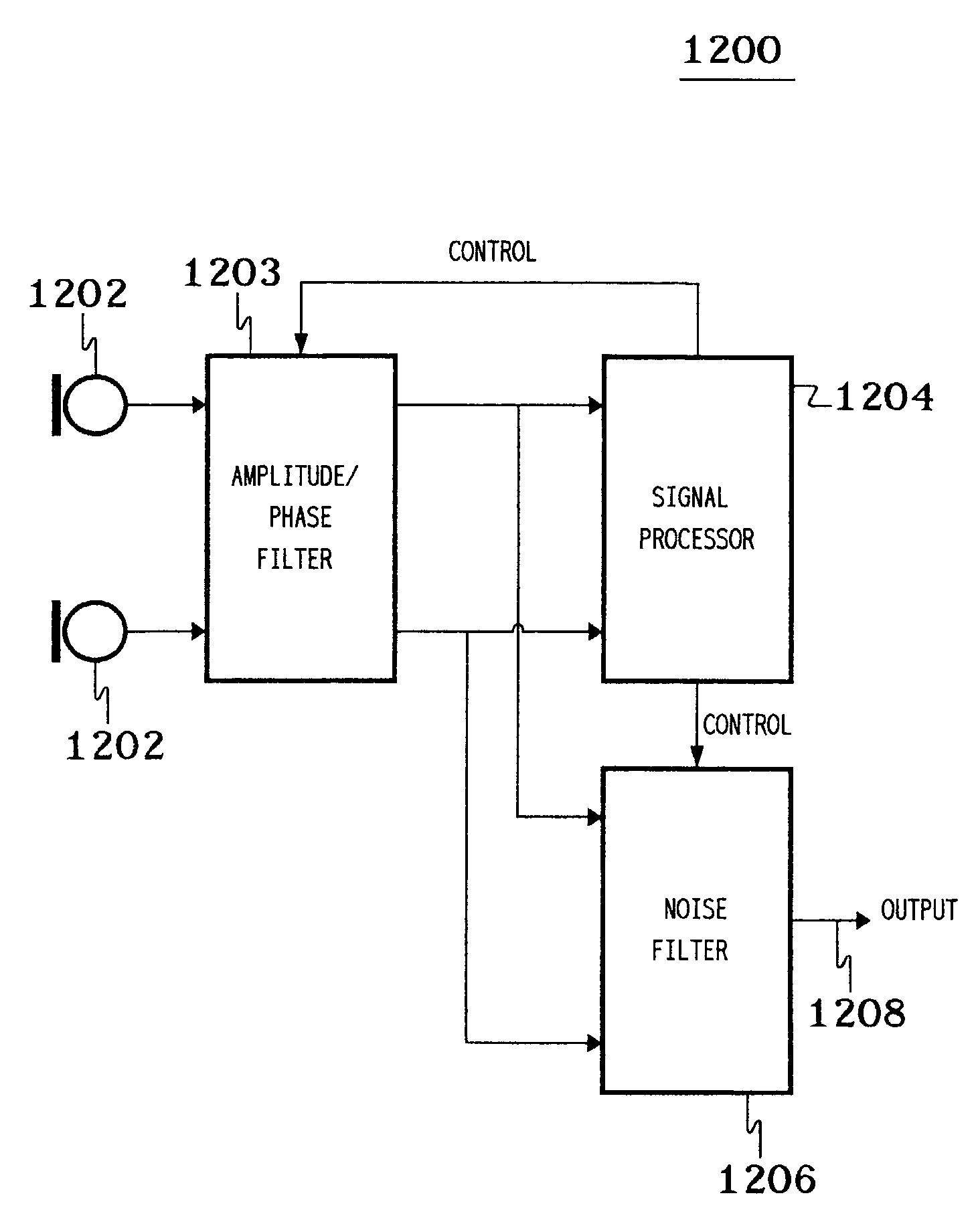
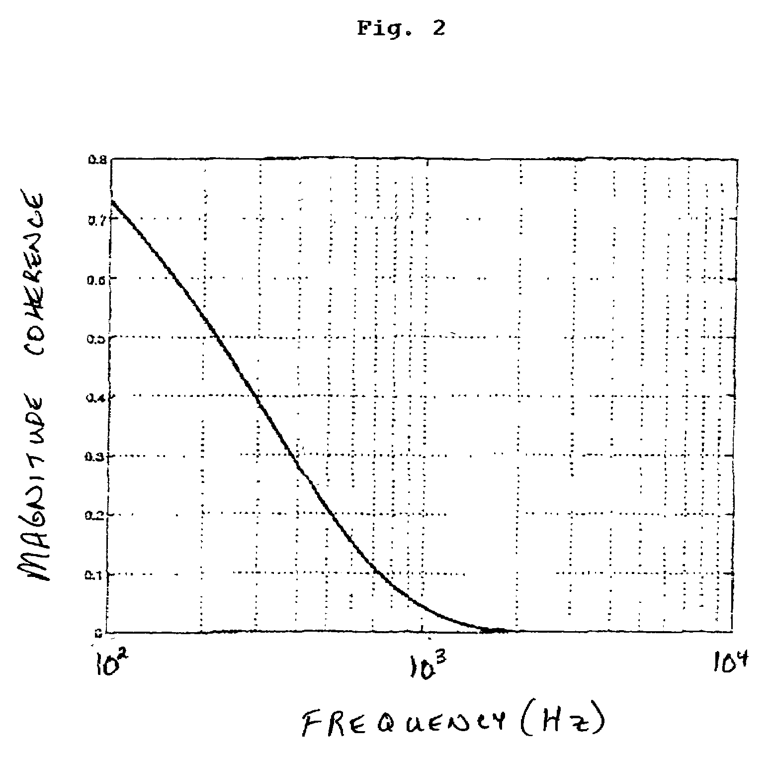
[0006]The present invention is related to signal processing techniques that attenuate noise, such as turbulent wind-noise, in audio signals without necessarily relying on the mechanical windscreens of the prior art. In particular, according to certain embodiments of the present invention, two or more microphones generate audio signals that are used to determine the portion of pickup signal that is due to wind-induced noise. These embodiments exploit the notion that wind-noise signals are caused by convective airflow whose speed of propagation is much less than that of the desired acoustic signals. As a result, the difference in the output powers of summed and subtracted signals of

Problems solved by technology

However, signals propagating at acoustic speeds will result in relatively large difference in the summed and subtracted signal powers.

Method used


Image

  • Reducing noise in audio systems
  • Reducing noise in audio systems
  • Reducing noise in audio systems

Examples


Embodiment Construction

Differential Microphone Arrays

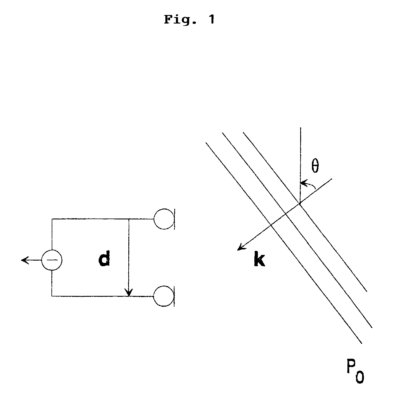
[0025]A differential microphone array is a configuration of two or more audio transducers or sensors (e.g., microphones) whose audio output signals are combined to provide one or more array output signals. As used in this specification, the term “first-order” applies to any microphone array whose sensitivity is proportional to the first spatial derivative of the acoustic pressure field. The term “nth-order” is used for microphone arrays that have a response that is proportional to a linear combination of the spatial derivatives up to and including n. Typically, differential microphone arrays combine the outputs of closely spaced transducers in an alternating sign fashion.

[0026]Although realizable differential arrays only approximate the true acoustic pressure differentials, the equations for the general-order spatial differentials provide significant insight into the operation of these systems. To begin, the case for an acoustic planewave propagating wi...


PUM


Abstract

Two or more microphones receive acoustic signals and generate audio signals that are processed to determine what portion of the audio signals result from (i) incoherence between the audio signals and / or (ii) audio-signal sources having propagation speeds different from the acoustic signals. The audio signals are filtered to reduce that portion of one or more of the audio signals. The present invention can be used to reduce turbulent wind-noise resulting from wind or other airjets blowing across the microphones. Time-dependent phase and amplitude differences between the microphones can be compensated for based on measurements made in parallel with routine audio system processing.

Description

CROSS-REFERENCE TO RELATED APPLICATIONS[0001]This application claims the benefit of the filing date of U.S. provisional application No. 60 / 354,650, filed on Feb. 2, 2002.BACKGROUND OF THE INVENTION[0002]1. Field of the Invention[0003]The present invention relates to acoustics, and, in particular, to techniques for reducing noise, such as wind noise, generated by turbulent airflow over microphones.[0004]2. Description of the Related Art[0005]For many years, wind-noise sensitivity of microphones has been a major problem for outdoor recordings. A related problem is the susceptibility of microphones to the speech jet, i.e., the flow of air from the talker's mouth. Recording studios typically rely on special windscreen socks that either cover the microphone or are placed between the mouth and the microphone. For outdoor recording situations where wind noise is an issue, microphones are typically shielded by acoustically transparent foam or thick fuzzy materials. The purpose of these wind...

Claims


Application Information

Patent Timeline
IPC IPC(8): H04R3/00H04R1/02H04R25/00
CPCH04R3/005H04R25/407H04R25/405H04R2430/21H04R2410/07
Inventor ELKO, GARY W.
Owner MH ACOUSTICS
Learn More