Method and apparatus for determining the intensity distribution of a radiation field

a radiation field and intensity distribution technology, applied in the field of methods and apparatus for determining the intensity distribution of a radiation field, can solve the problems of difficult for hospital physicists to carry out their duties within the constraints of working time and existing personnel resources, and the time-consuming use of quality control measurements of patient-care equipment using present equipment, etc., to achieve the effect of improving the position precision of the apparatus, small shielding effect, and improving the position precision

Inactive Publication Date: 2007-01-30
GAMMAPRO
View PDF8 Cites 17 Cited by
  • Summary
  • Abstract
  • Description
  • Claims
  • Application Information

AI Technical Summary

Benefits of technology

[0012]The present invention is intended to create an entirely new type of apparatus suitable for monitoring the quality of patient-care equipment, which can be used to make measurements of both static and dynamic radiation fields easily and rapidly, and which eliminates the possibility of human error in dosimetric measurement. The invention also relates to a method for use in the apparatus, which permits the shape of a high-energy radiation field to be determined using the operating principle of an ionization chamber. The characteristic features of the method for determining the intensity distribution of a radiation field, in which the ionization caused by the radiation field is detected by means of parallel ionization detector planes arranged in an ionization chamber, two of which planes are formed of series of wires determining the position of the ionization event in the X and Y directions, which detector planes provide the X and Y co-ordinates X1, Y1 of the ionization event, is characterized in that the ionization event is created by means of the photonuclear reaction products arising from the radiation.
[0014]In the method according to the invention, photonuclear reactions arising from radiation are used to determine the shape of a radiation field. The apparatus includes a photonuclear reaction converter. According to one preferred embodiment, the direction of travel of the photonuclear reaction products is collimated. This improves the position precision of the apparatus. According to another preferred embodiment, the photonuclear reaction converter can be formed of layers of one or several substances, making it possible to change the energy area and the intensity sensitivity being investigated with the apparatus.
[0015]The apparatus according to the invention will, among other things, make the work of hospital personnel significantly more meaningful and motivated, because the measurement event itself will be considerably faster than when using presently known apparatuses.
[0016]Compared to the state of the art, by using the apparatus according to the invention a real-time image of the radiation field is created rapidly with a single measurement. This also permits the time dependencies of the dynamic fields achieved using present patient-care technology to be determined and allows the apparatus to be neutral to changes taking place in the environment. The measurement is thus considerably more reliable and its position precision is better than in the state of the art. In addition to this, the shape of the field can be changed in real time, by adjusting the accelerator and its parameters.
[0017]The apparatus according to the invention is unaffected by radiation damage and achieves the additional advantages of, among other things, a small shielding effect and easily arranged measurement of even extensive radiation fields. It is also characterized by the simplicity and cheapness of its electronics, in comparison to apparatuses based on the state of the art. The other characteristic features of the apparatus according to the invention will become apparent from the accompanying claims.

Problems solved by technology

Together with changes in the conditions and demands of this work, the development of external radiotherapy methods, accelerators, and equipment relating to the radiotherapy chain has brought new challenges for those working with radiotherapy.
It is difficult for hospital physicists to carry out their duties within the constraints of working time and existing personnel resources.
The complexity of the measuring devices and the preparations required by measurements mean that making quality control measurements of patient-care equipment using present equipment is also time consuming.
Making measurements takes up the entire working time of hospital physicists, leaving them no time to carry out any other tasks.
In addition, the measurements specified in a quality-control program for radiotherapy equipment cannot be made during normal working time, as the equipment is being used for therapy at that time.
Any increase in the number of detectors will significantly raise the price of the device and the amount of complex electronics required.
It is difficult to compensate later for the measurement error that this creates and which in any event reduces the reliability of the measurement.
In addition to the above, due to the measurement principle of sweeping the radiation field of the detectors, the water phantom according to the state of the art cannot measure the intensity distribution of a field independently of time.
The position resolution ability of these devices is poor, being several centimeters, and they are unable to measure small variations in position in a dynamic field.
The fact that known devices are out of date can also be seen in their quite simple user interfaces.
However, apparatus of this type has only a poor ability to determine in real time the shape of the radiation fields of modern high-energy radiotherapy devices creating dynamic fields.

Method used


Image

  • Method and apparatus for determining the intensity distribution of a radiation field
  • Method and apparatus for determining the intensity distribution of a radiation field
  • Method and apparatus for determining the intensity distribution of a radiation field

Examples


Embodiment Construction

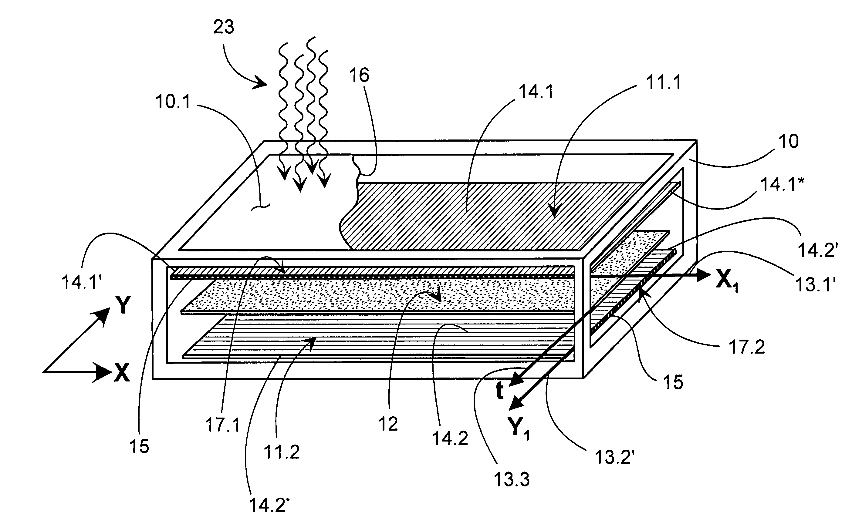
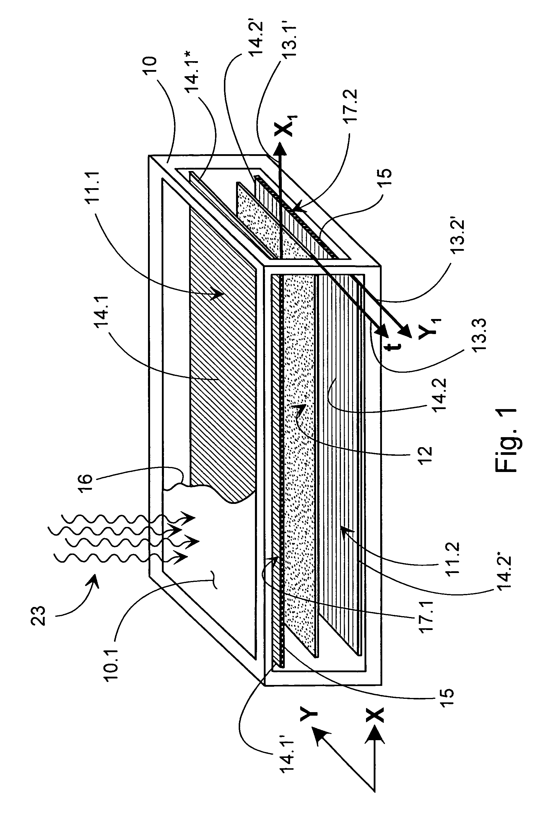
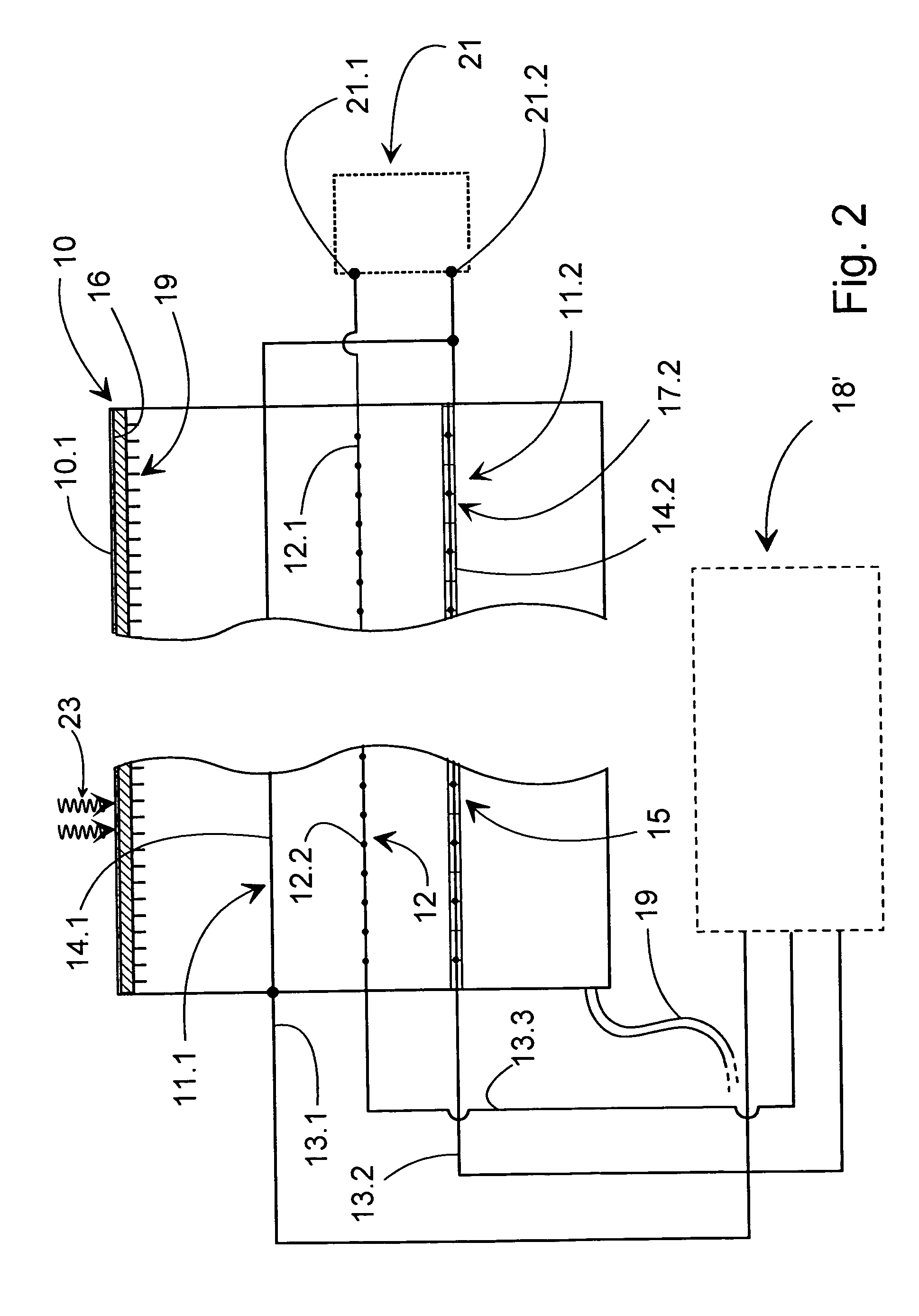
[0025]FIGS. 1 and 2 show the simplified operating principle of one embodiment of the apparatus according to the invention. The case of the apparatus is formed by an ionization chamber 10, which is, for example, 30-cm long and 1-cm high. The ionization chamber 10 is filled with an ionizing gas, such as n-pentane, as a negative pressure. Inert gases, carbon hydrides, and generally compounds of them can be used as the filler gas of the chamber 10. The use of a negative pressure (for example, 1–6 Torr) results in the ionization chamber 10 having, in reality, slightly rounded sides.

[0026]In the embodiment shown in FIGS. 1 and 2, a mesh-like lo detector plane 12, which acts as a cathode plane rejecting electrons and attracting positive gas molecules and ions, and is formed from wires 12.1, 12.2, for example, of wolfram (wire diameter 100 μm), connected to the negative potential 21.1 of a power supply 21, is located in the ionization chamber 10. A signal wire 13.3 is connected to the catho...


PUM


Abstract

The invention relates to a method and apparatus for determining the intensity distribution of a radiation field. In the method, the ionization caused by the radiation field is detected by parallel ionization detector planes arranged in an ionization chamber, two of which planes are formed of series of wires determining the position of an ionization event in the X and Y directions, which detector planes provide the X and Y co-ordinates X1, Y1 of the ionization event. The ionization event is created by photonuclear reaction products arising from the radiation.

Description

TECHNICAL FIELD[0001]The present invention relates to a method and apparatus for determining the intensity distribution of a radiation field, which apparatus includes at least two parallel ionization detector planes arranged in an ionization chamber, which are arranged to be formed of a series of wires determining the location of an ionization event in an X and an Y direction, and in which the detector planes are connected to measurement electronics, in such a way that the said two detector planes are arranged to provide the X and Y co-ordinates of the ionization event.BACKGROUND OF THE INVENTION[0002]The regular and sufficiently accurate and careful performance of measurement and other quality-control measures for patient-care equipment, is the foundation of reliable radiotherapy. Together with changes in the conditions and demands of this work, the development of external radiotherapy methods, accelerators, and equipment relating to the radiotherapy chain has brought new challenge...

Claims


Application Information

Patent Timeline
IPC IPC(8): G01T1/18A61N5/10G01T1/29G01T1/185
CPCG01T1/185
Inventor VIRTANEN, ARI
Owner GAMMAPRO
Why Eureka
Try Eureka