Abnormality diagnosis apparatus and engine cooling system having the same

a technology of abnormality diagnosis and engine cooling, which is applied in the direction of machines/engines, electrical control, instruments, etc., can solve the problem that there has not been established a technique for accurately diagnosing the existence of abnormality of the flow rate control valve, and achieve the effect of accurately determining the existence of abnormality

Inactive Publication Date: 2007-01-30
DENSO CORP
View PDF12 Cites 16 Cited by
  • Summary
  • Abstract
  • Description
  • Claims
  • Application Information

AI Technical Summary

Benefits of technology

[0007]The present invention addresses the above disadvantage. Thus, it is an objective of the present invention to provide an abnormality diagnosis apparatus for diagnosing abnormality of a cooling sys

Problems solved by technology

However, in such a cooling system having the flow rate control valve, there has not been establis

Method used


Image

  • Abnormality diagnosis apparatus and engine cooling system having the same
  • Abnormality diagnosis apparatus and engine cooling system having the same
  • Abnormality diagnosis apparatus and engine cooling system having the same

Examples


Embodiment Construction

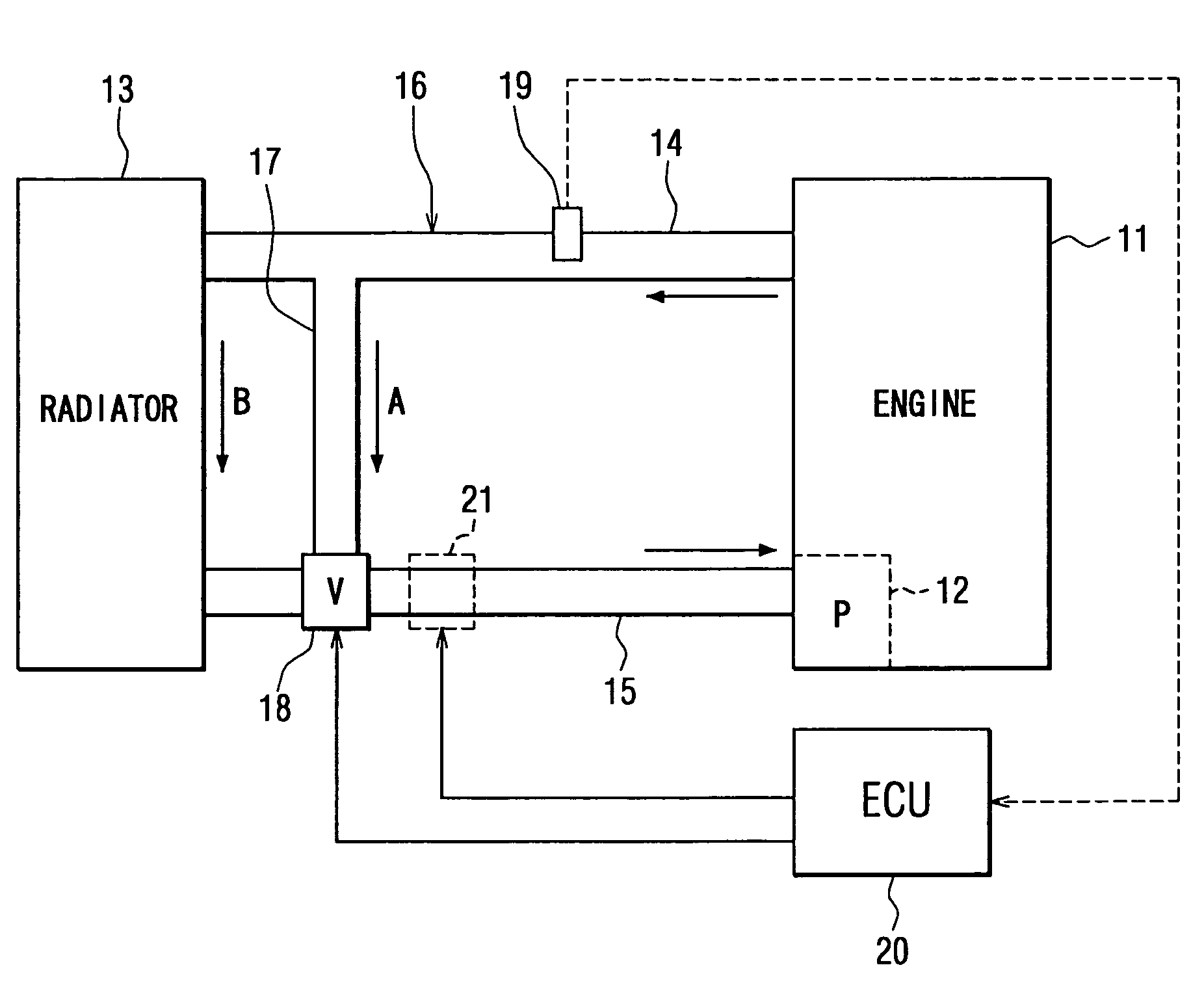
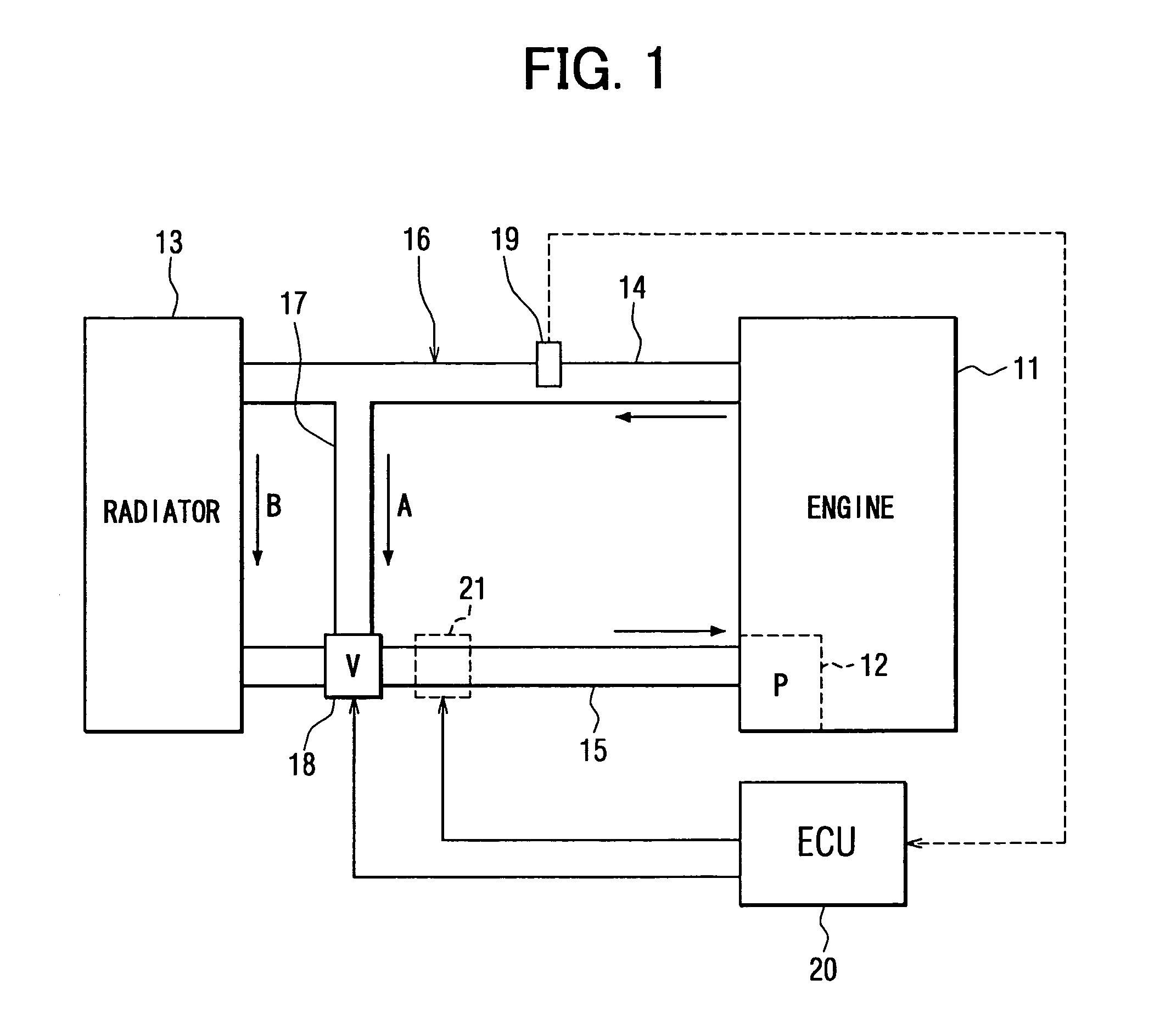
[0017]An embodiment of the present invention will be described with reference to the accompanying drawings. First, a structure of an entire cooling system having an abnormality diagnosis apparatus will be schematically described with reference to FIG. 1. A mechanical water pump 12, which is driven by drive force of an engine (internal combustion engine) 11, is arranged in an inlet of a coolant passage (water jacket) of the engine 11. A coolant circulation line (first coolant circulation line) 14 connects between an outlet of the coolant passage of the engine 11 and an inlet of a radiator 13, and a coolant circulation line (second coolant circulation line) 15 connects between an outlet of the radiator 13 and an inlet of the mechanical water pump 12. Thus, there is constructed a circulation line system (coolant circuit) 16, in which coolant is circulated through the coolant passage of the engine 11, the coolant circulation line 14, the radiator 13, the coolant circulation line 15, the...


PUM


Abstract

A coolant temperature of coolant in a circulation line system is measured through a coolant temperature sensor and is controlled by controlling a flow rate control valve. The flow rate control valve is diagnosed to determine whether abnormality of the flow rate control valve exists based on behavior of the measured coolant temperature, which is measured through the coolant temperature sensor during a warm-up period of an internal combustion engine.

Description

CROSS REFERENCE TO RELATED APPLICATION[0001]This application is based on and incorporates herein by reference Japanese Patent Application No. 2002-240894 filed on Aug. 21, 2002.BACKGROUND OF THE INVENTION[0002]1. Field of the Invention[0003]The present invention relates to an abnormality diagnosis apparatus and an engine cooling system having the same.[0004]2. Description of Related Art[0005]In a previously proposed engine cooling system, a bypass fluid line, which conducts coolant and bypasses a radiator, is provided. Furthermore, a thermostat valve, which switches a flow of coolant between the bypass fluid line and a fluid line connected to the radiator, is provided. When a coolant temperature is lower than a predetermined threshold temperature, which indicates an end point of an engine warm-up period, the thermostat valve is controlled to close the fluid line, which leads to the radiator, and opens the bypass fluid line to circulate the coolant through the bypass fluid line.[0006...

Claims


Application Information

Patent Timeline
IPC IPC(8): F02D45/00F01P7/14F01P11/18F01P7/16F01P11/16
CPCF01P11/16F01P7/167F01P2025/32F01P2007/146
Inventor WAKAHARA, KEIJI
Owner DENSO CORP
Why Eureka
Try Eureka