
Pool table carriage

Inactive Publication Date: 2007-01-16
BRATTON SR JOHN J
View PDF11 Cites 32 Cited by
  • Summary
  • Abstract
  • Description
  • Claims
  • Application Information

AI Technical Summary

Benefits of technology

[0007]It is an object of the invention to produce a pool table carriage for supporting and transporting a pool table between various locations without damaging the pool table. Accordingly, the pool table carriage has two support plate assemblies, each capable of selectively supporting one of the legs of the pool table, and each having wheels for allowing the pool table carriage to be selectively rolled between various locations without damaging the pool table.
[0010]The invention is a pool table carriage for supporting a pool table at an elevated position above a horizontal support structure, and for transporting the pool table between locations without damaging the pool table. The pool table carriage comprises two support plate assemblies and a main frame interposed therebetween. Each support plate assembly selectively supports one of the legs of the pool table, when the pool table carriage is being deployed. Each support plate assembly further has four selectively extendable rotatable jackscrews, and two wheel assemblies each having wheels. The jackscrews are extendable in two opposite directions. Rotation of the jackscrew in one direction causes the jackscrew to retract upward, thereby allowing the wheels to contact the support structure, thereby allowing the pool table carriage to roll between different locations. Rotation of the jackscrew in the other direction causes the jackscrew to extend downward, thereby raising the wheels above the support structure, thereby immobilizing the pool table carriage.

Problems solved by technology

Rotation of the jackscrews in one of these directions causes the jackscrews to extend downward and engage the support structure, thereby lifting the wheels and immobilizing the pool table carriage upon the support structure, after the pool table carriage has been moved to a desired location.
Rotation of the jackscrew in the other direction causes the jackscrew to extend downward, thereby raising the wheels above the support structure, thereby immobilizing the pool table carriage.

Method used


Image

  • Pool table carriage
  • Pool table carriage
  • Pool table carriage

Examples


Embodiment Construction

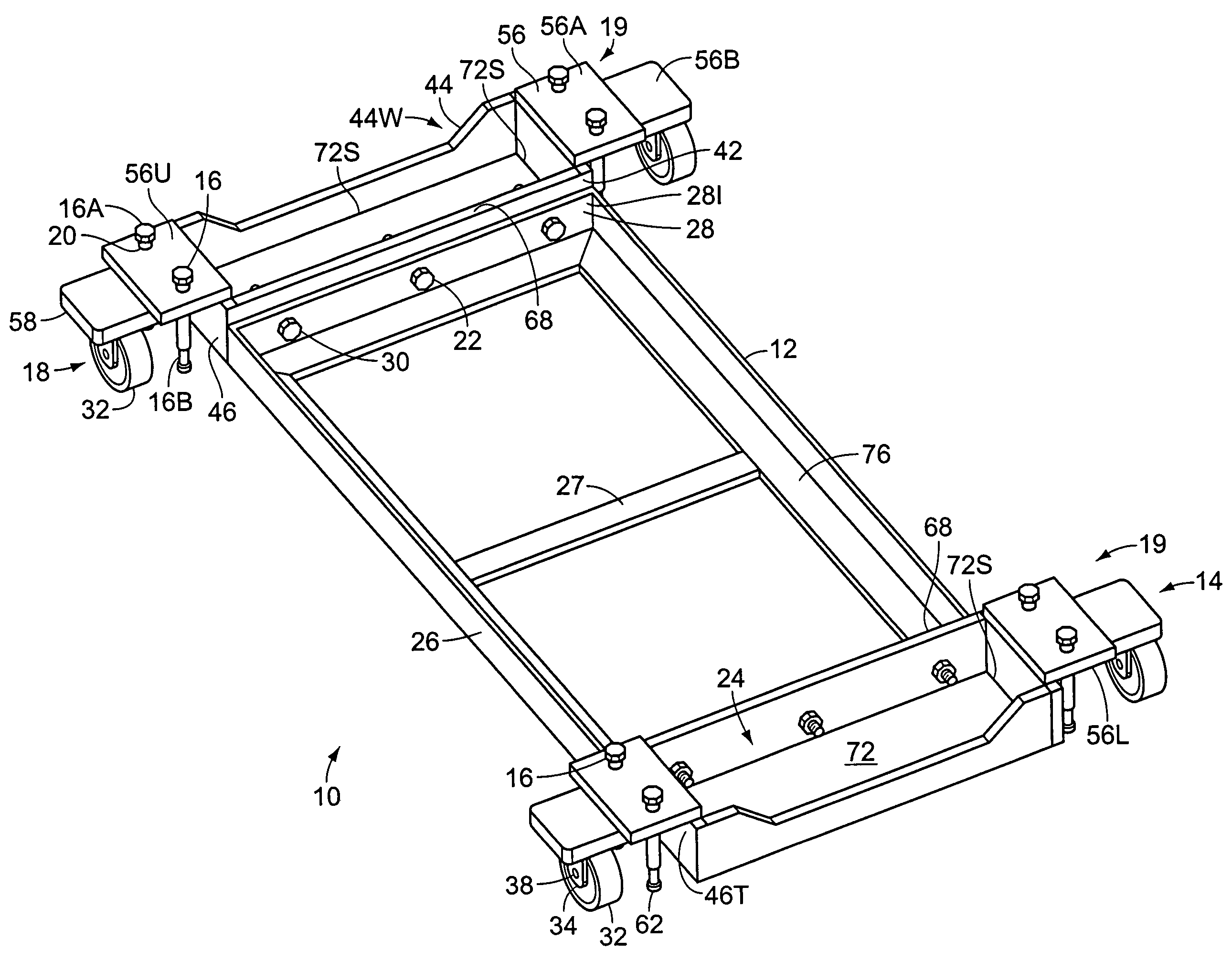
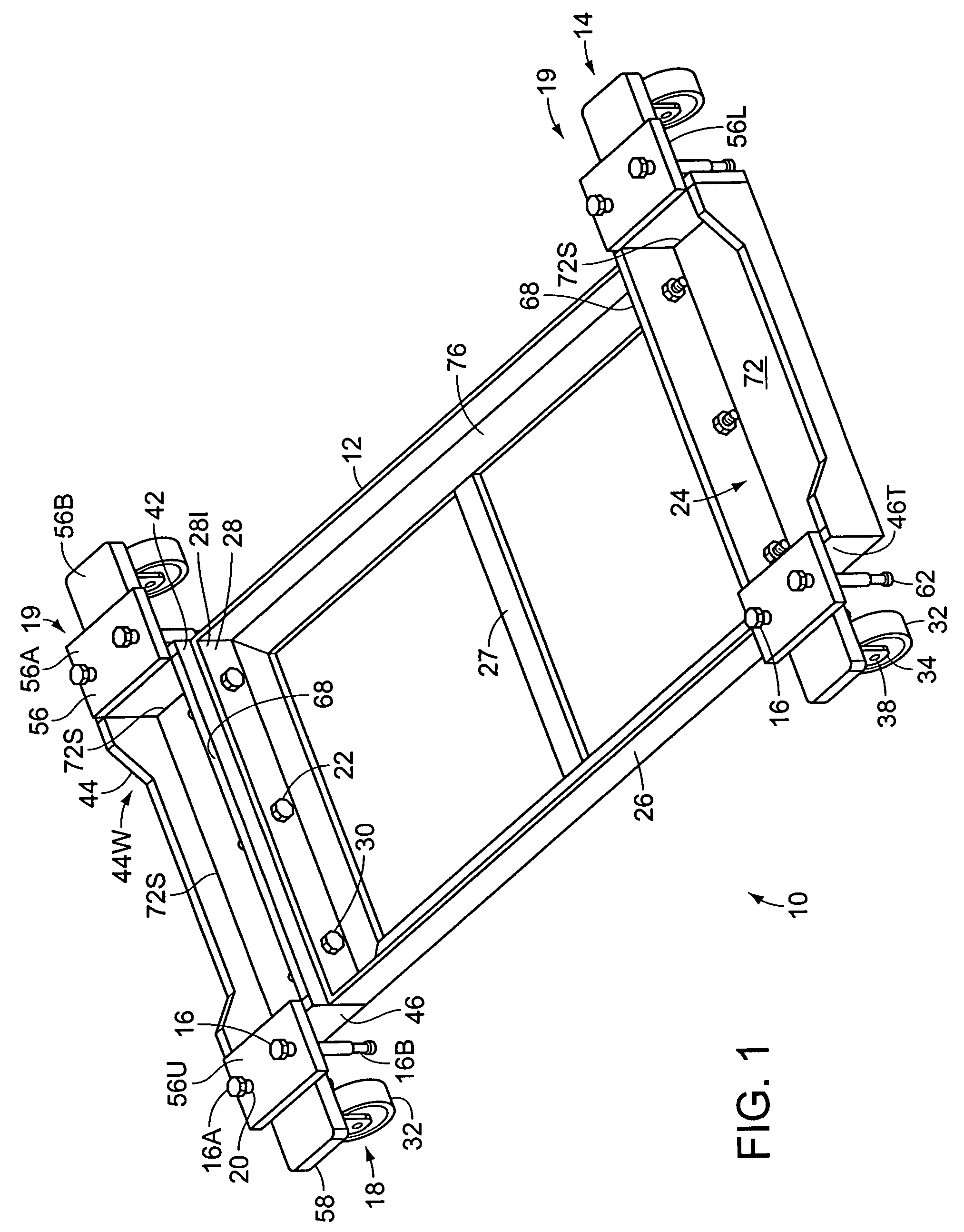
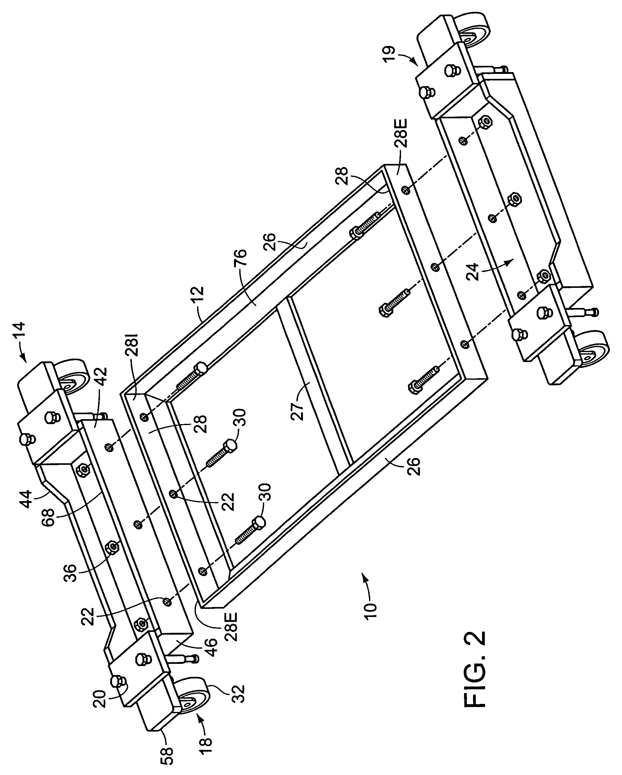
[0018]FIG. 1 illustrates a pool table carriage 10, comprising two support plate assemblies 14 and a main frame 12 interposed therebetween. The pool table carriage 10 is used in conjunction with a pool table having two long sides, two short sides, a playing surface, and two legs for supporting said sides and said playing surface at an elevated position above a horizontal support structure such as a floor. The main frame 12 selectively and rigidly attaches the two support plate assemblies 14 to one another, as will be described. Each of the substantially rectangular support plate assemblies 14 is substantially identical. Hence, a description of one of the support plate assemblies 14 will suffice as a description of the other.

[0019]Each support plate assembly 14 has a substantially rectangular horizontal base 72 having four edges 72S. The support plate assembly 14 has an interior wall 68, an exterior wall 44, and two connecting walls 46 each having a top 46T, each of said walls 68, 44,...


PUM


Abstract

A pool table carriage for supporting a pool table at an elevated position above a horizontal support structure, and for transporting the pool table between locations without damaging the pool table. The pool table carriage comprises two support plate assemblies and a main frame interposed therebetween. Each support plate assembly selectively supports one of the legs of the pool table, when the pool table carriage is being deployed. Each support plate assembly further has four selectively extendable rotatable jackscrews, and two wheel assemblies each having wheels. The jackscrews are extendable in two opposite directions. Rotation of the jackscrew in one direction causes the jackscrew to retract upward, thereby allowing the wheels to contact the support structure, thereby allowing the pool table carriage to roll between different locations. Rotation of the jackscrew in the other direction causes the jackscrew to extend downward, thereby raising the wheels above the support structure, thereby immobilizing the pool table carriage.

Description

BACKGROUND OF THE INVENTION[0001]1. Field of the Invention[0002]The invention generally relates to a carriage for supporting and transporting heavy items, and in particular it relates to a carriage for supporting and transporting a pool table.[0003]2. Description of the Related Art[0004]Many millions of people play the game of pool, which requires a pool table. Pool tables are large, expensive items and are susceptible to damage while being moved between locations. Installing a pool table, however, is a major commitment of floor space. In addition to the space occupied by the table itself, considerable space must be left around the pool table. Accordingly, it is generally placed in the middle of a room. At times, however, it would be desirable to move the pool table away from the middle of the room, and toward the perimeter of the room. The pool table, however, is generally too heavy to allow such movement. In addition, the high risk of damage makes such frequent moves undesirable. ...

Claims


Application Information

Patent Timeline
IPC IPC(8): A63B71/00
CPCA63D15/00B62B5/0083A63B2243/002B62B2202/30B62B5/049
Inventor BRATTON, SR., JOHN J.
Owner BRATTON SR JOHN J
Learn More