
Control system and method for mitigating transients in a machine due to occasional maintenance or service

Inactive Publication Date: 2007-01-09
XEROX CORP
View PDF8 Cites 6 Cited by
  • Summary
  • Abstract
  • Description
  • Claims
  • Application Information

AI Technical Summary

Benefits of technology

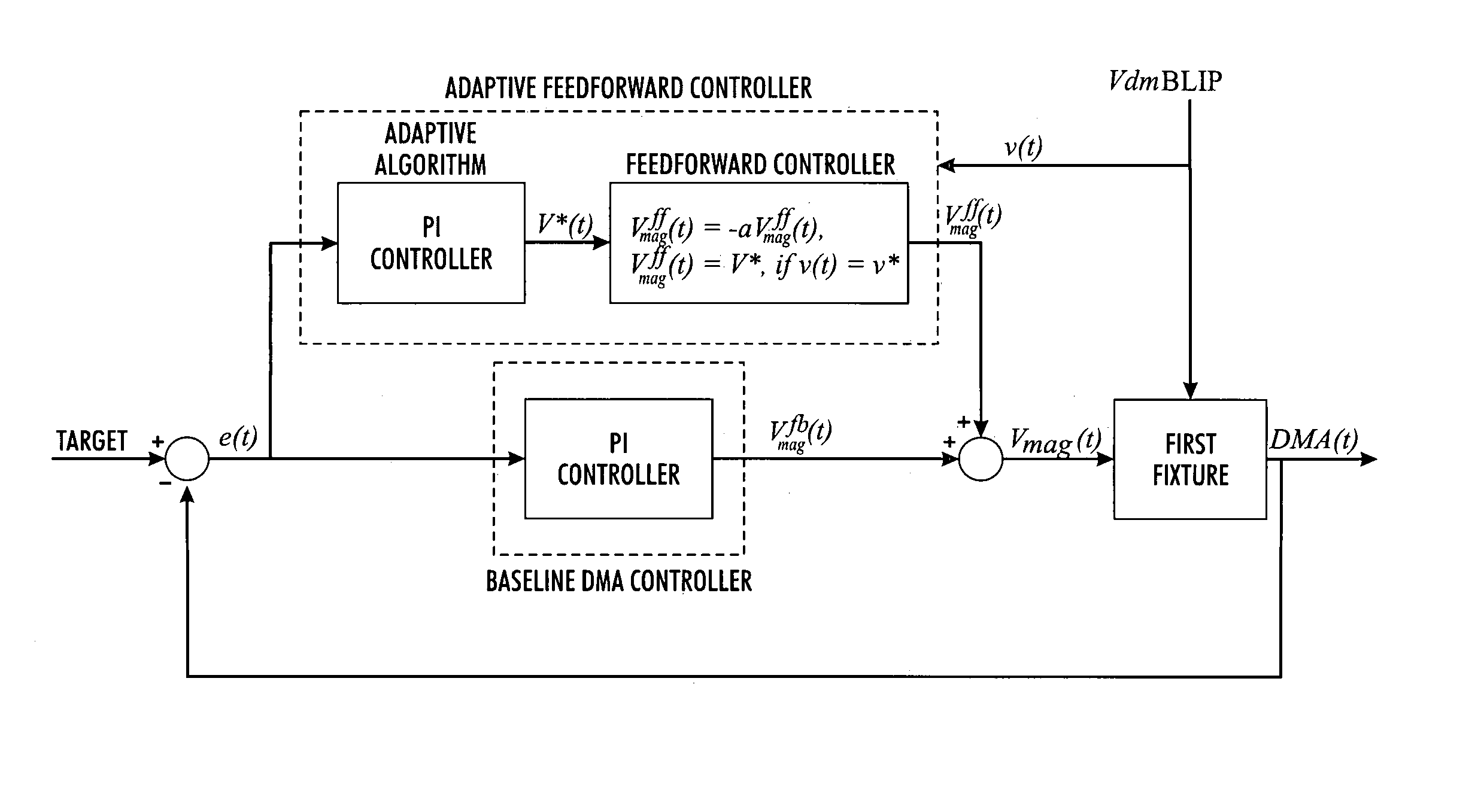
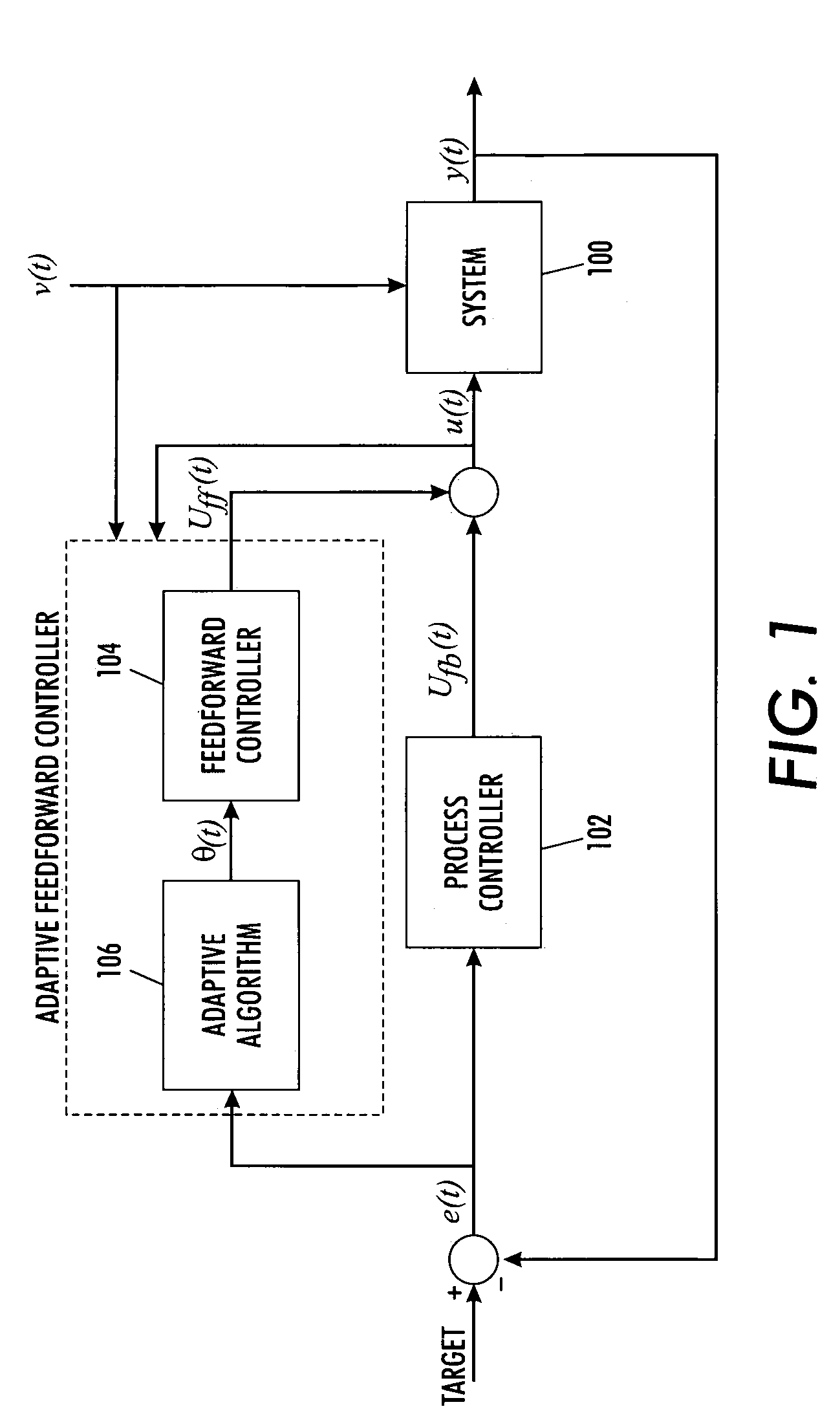
[0007]The exemplary embodiments predict how the machine will respond to maintenance, feed this prediction forward to process controls to make adjustments just prior to the maintenance cycle, and update or adapt the prediction of adjustments needed for the next maintenance cycle to correct for transients following the next maintenance cycle, based on both the current and past performance immediately following the maintenance cycle. Thus, by anticipating the effect maintenance may have on a machine instead of only reacting to it, the benefits of the maintenance can be realized without the expense of transient deviations from target.
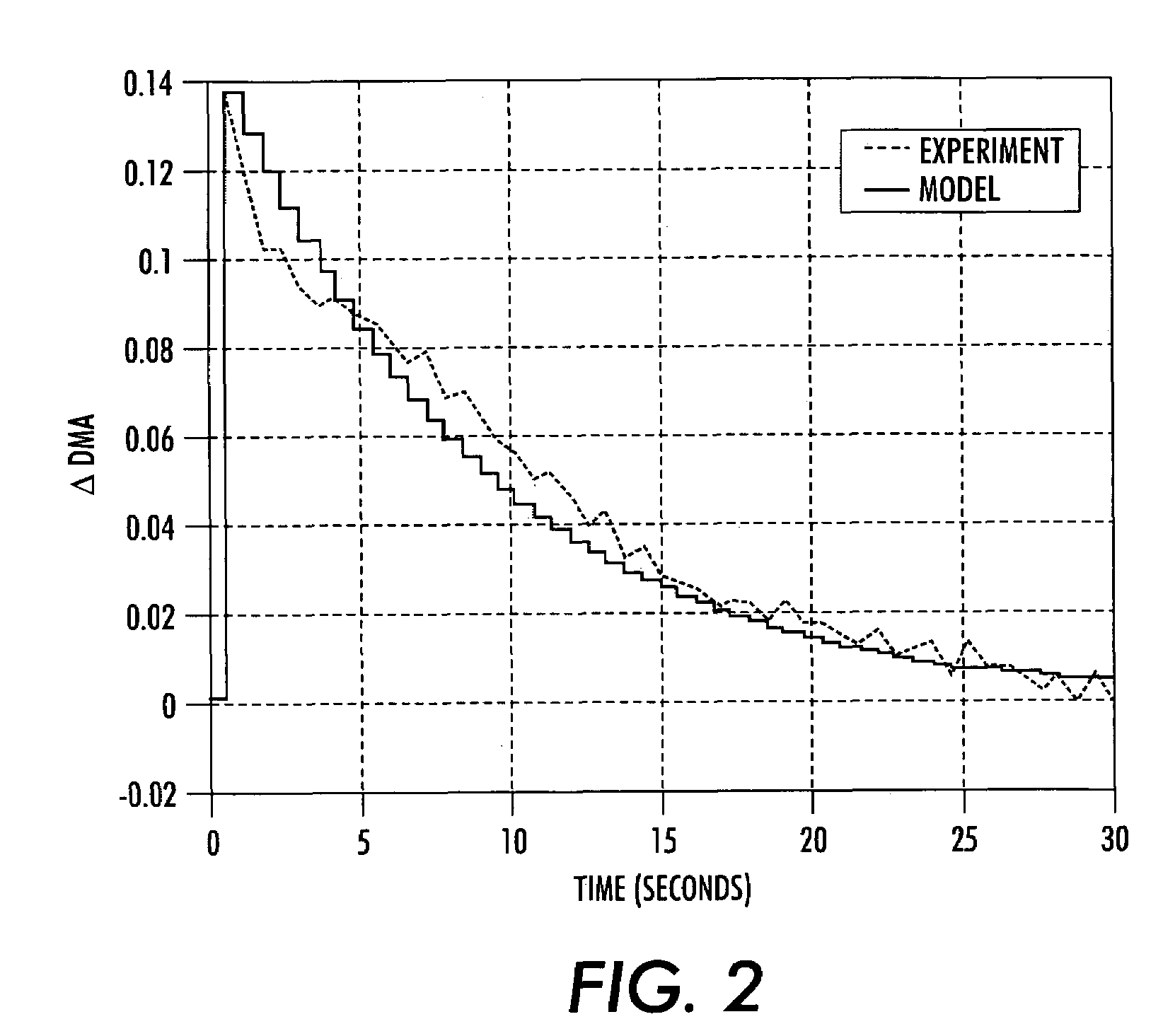
[0029]This method for mitigating transients in machine performance due to periodic or occasional maintenance action also includes varying the Vmag with the controller after a Vdm blip routine to mitigate DMA transients induced by the blip routine.
[0031]This method for mitigating transients in machine performance due to periodic or occasional maintenance action also includes varying Vcharge and ROS intensity with the controller to mitigate TRC variations included by the Vdm blip cycle, wherein Vcharge and ROS intensity are updated between blip cycles.

Problems solved by technology

In other words, the process controls of a machine may view maintenance as a disturbance and the machine output may significantly deviate from target as the process controls readjust to the machine post-maintenance.
Accordingly, the machine may need to be down until the transients subside, and if the maintenance is frequent enough, the machine efficiency may be severely impacted.

Method used


Image

  • Control system and method for mitigating transients in a machine due to occasional maintenance or service
  • Control system and method for mitigating transients in a machine due to occasional maintenance or service
  • Control system and method for mitigating transients in a machine due to occasional maintenance or service

Examples


specific example — 1

SPECIFIC EXAMPLE—1

[0056]A concept of adaptive feedforward control is applied to a problem of mitigating developed mass transients resulting from interactions between periodic donor roll and wire maintenance and electrostatic process controls, as described above. Most of the analyses and experiments presented below may be easily generalized to other fixtures.

First Fixture

[0057]A first fixture may include a single hybrid scavengeless development housing that is capable of solid area development. An enhanced toner area coverage sensor is used to measure developed patches, e.g., patches of toner that have been deposited on and affixed to a substrate, in-situ and in real-time. For a sample printer, electrostatic process controls use three actuators, a magnetic roll voltage, a laser power, and a charge level on the photoreceptor, to control three targets along a tone reproduction curve. Since the first fixture is only a solid area development fixture, the analogue to the electrostatic pro...


PUM


Abstract

A control system and method of predicting how a machine will respond to occasional or periodic service, and adjusting the machine accordingly to account for the change in machine behavior due to the service, mitigates transients in machine performance. A prediction of the service effect is fed forward to the existing control system just prior to the occurrence of service in order to compensate for the service effect. This prediction is continually updated and refined using subsequent measurements of the effect of service on machine performance. More specifically, a controller monitors the process output variables indicative of the machine performance and adjusts machine inputs to achieve a desired level of machine performance. The controller monitors the process output variables indicative of the machine performance prior to, during, and immediately after the service and adjusts the machine inputs to compensate for the transients.

Description

[0001]This is a continuation-in-part application of U.S. application Ser. No. 11 / 169,756 filed on Jun. 30, 2005 now U.S. Pat. No. 7,123,850, which is hereby incorporated by reference in its entirety.BACKGROUND[0002]The exemplary embodiments are directed to a machine or process that is subject to periodic or occasional maintenance or service.[0003]The related art includes machines, such as, for example, a copier, a printer, or the like that are under a closed-loop feedback control. If a machine is subject to occasional or periodic maintenance or service, the effect of the maintenance or service may change the machine and / or the control process of the machine. Such maintenance or service may include cleaning, repair, part replacement, or the like. A change to the machine due to maintenance can have a large impact on the machine response and hence the closed-loop behavior of the system. For example, under closed-loop control, the machine inputs may be at certain values in order to keep...

Claims


Application Information

Patent Timeline
IPC IPC(8): G03G15/00
CPCG03G15/5037G03G2221/0005
Inventor LESTRANGE, JACK T
Owner XEROX CORP
Learn More