
Electrical connection system

a technology of electrical connection system and connection plate, which is applied in the direction of coupling device connection, coupling base/case, electrical apparatus, etc., can solve the problems of high cost, high cost of electrical installation, and inability to work cheaply

Inactive Publication Date: 2007-01-09
STEPHAN GERARD D
View PDF17 Cites 111 Cited by
  • Summary
  • Abstract
  • Description
  • Claims
  • Application Information

AI Technical Summary

Benefits of technology

[0017]The supply connector clamp may have a supply clamp proximal end and a supply clamp distal end. The supply connector clamp may be fastened to the supply connector base such that the line conductor, the ground conductor, and the neutral conductor are substantially prevented from withdrawing from the supply connector housing.

Problems solved by technology

The drawbacks to manually connecting each wire to a terminal on a receptacle or switch are numerous.
The foremost being the great expense.
Electrical installations are costly for many reasons, but two reasons predominate.
Due to the demand for electricians, particularly for the knowledge they possess, they do not work cheaply.
Secondly, the amount of time required to complete an electrical installation is great.
The majority of the time is spent performing labor intensive tasks.
Beside the cost, other drawbacks to manually terminating each wire are common.
One is that the improper termination of wires is an electrical hazard.
Improper termination may include connecting the wire to the wrong location, or it may include terminating the wire at the proper location but not fastening the wire tightly enough so that a loose connection results.
Potential users of an improperly wired receptacle may be injured.
In addition, improper wiring can result in fire.
Also known to installers is insufficient room in the junction box for excess wire length plus the receptacle.
If the installer cuts the wire too short, they will not have enough wire to work with or will have to pull another wire through a finished wall.
If the wire is too long, there will not be enough space inside the junction box for the wire and the receptacle.
Additionally, there remains an unfulfilled need to provide an electrical connection system which can be used to quickly and easily expand an existing electrical system that does not require an in depth understanding of electrical wiring.

Method used


Image

  • Electrical connection system
  • Electrical connection system
  • Electrical connection system

Examples


Embodiment Construction

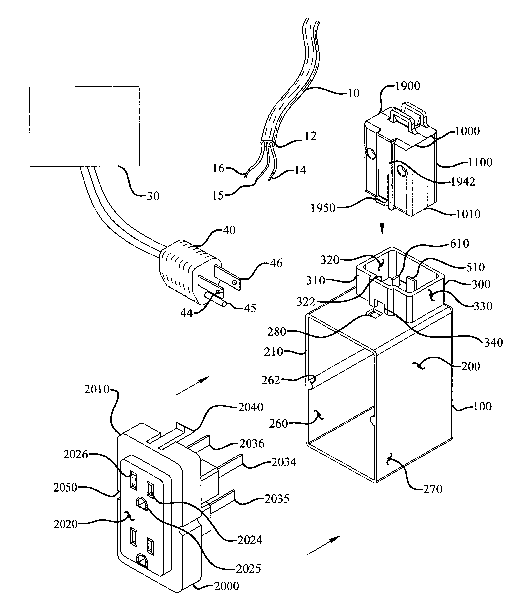
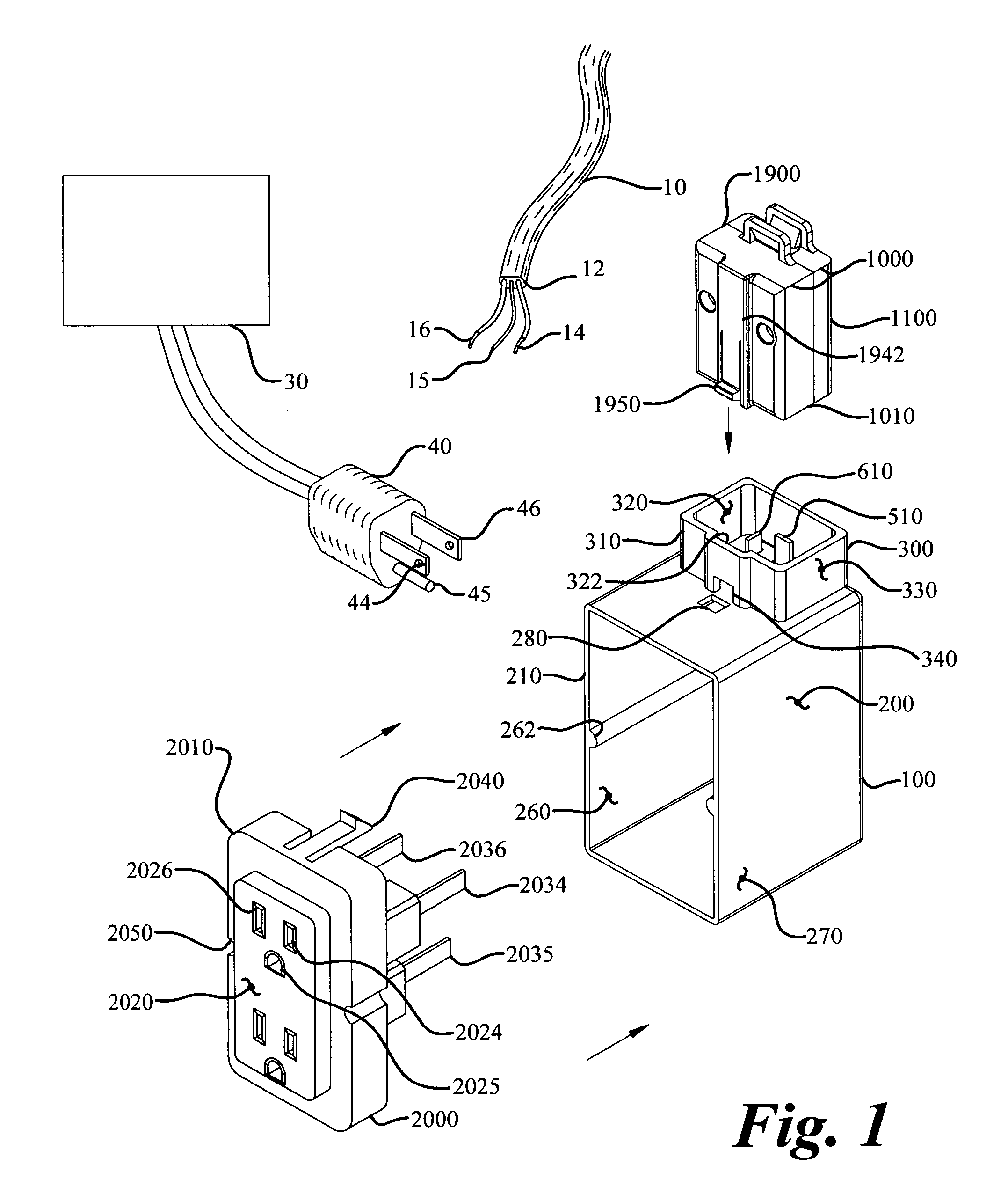
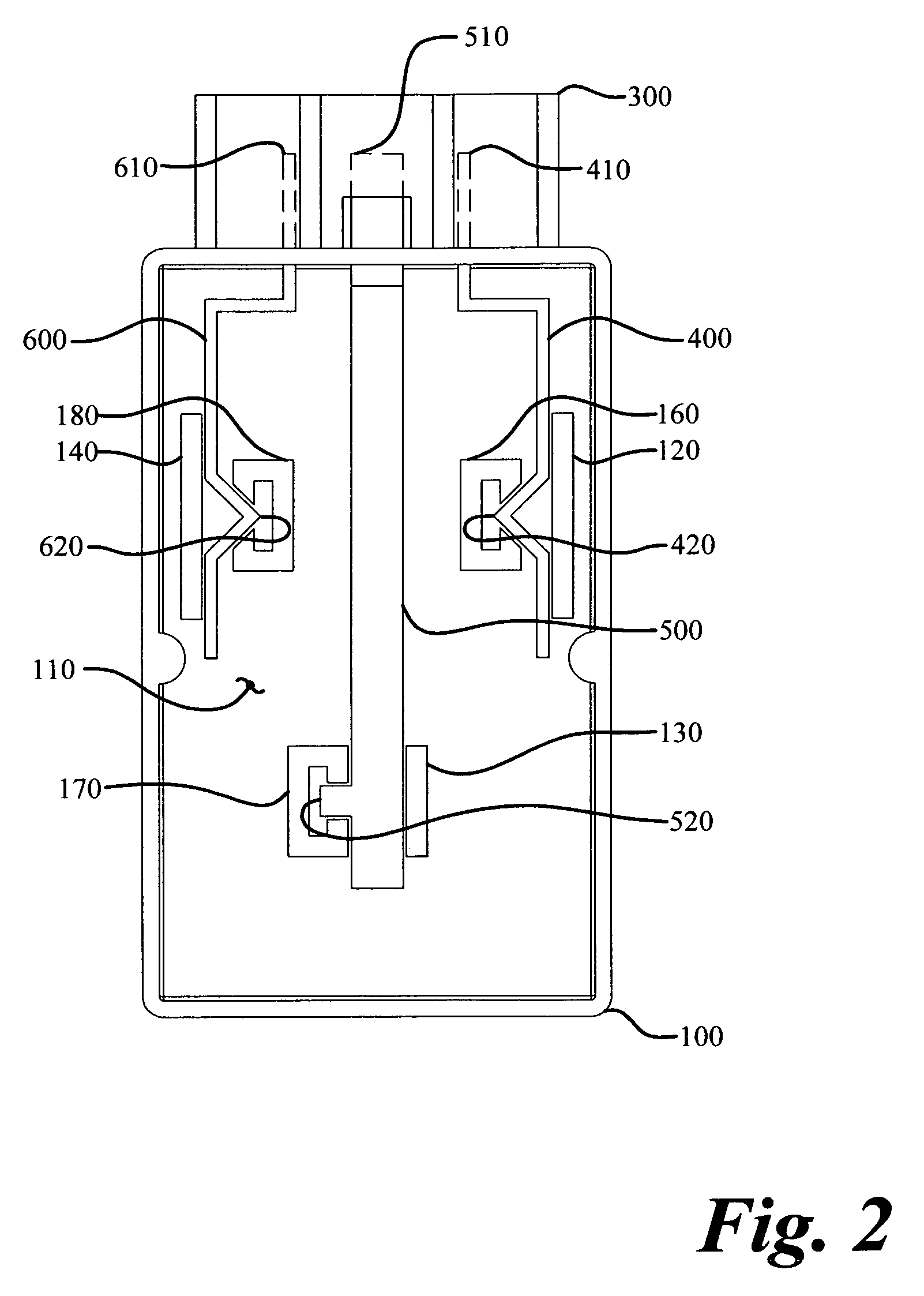
[0043]The electrical connection system (50) of the instant invention enables a significant advance in the state of the art. The preferred embodiments of the device accomplish this by new and novel arrangements of elements and methods that are configured in unique and novel ways and which demonstrate previously unavailable but preferred and desirable capabilities. The detailed description set forth below in connection with the drawings is intended merely as a description of the presently preferred embodiments of the invention, and is not intended to represent the only form in which the present invention may be constructed or utilized. The description sets forth the designs, functions, means, and methods of implementing the invention in connection with the illustrated embodiments. It is to be understood, however, that the same or equivalent functions and features may be accomplished by different embodiments that are also intended to be encompassed within the spirit and scope of the in...


PUM


Abstract

An electrical connection system designed to connect electrical conductors to a junction box containing a receptacle. The system incorporates a junction box, a supply connector, a distribution connector, and a receptacle. The junction box includes a line bus, a ground bus, and a neutral bus. The supply connector adapts the incoming electrical wire having a line conductor, a ground conductor, and a neutral conductor for connection to the line bus, the ground bus, and the neutral bus. The electrical receptacle is formed with a line blade, a ground blade, and a neutral blade which, respectively, electrically connect to the line bus, the ground bus, and the neutral bus. Electrical energy may be supplied through the electrical conductors to the electrical receptacle. A distribution connector may be incorporated to supply electrical energy to downstream receptacles.

Description

TECHNICAL FIELD[0001]The instant invention relates to installation systems for connecting electrical wiring to electrical receptacles, and, more particularly, to an electrical connection system having a supply connector, a junction box, and a receptacle, that provides a system for installing electrical receptacles in a quick, safe, and inexpensive fashion.BACKGROUND OF THE INVENTION[0002]The most common method of installing electrical wiring and receptacles is by manually connecting each wire to its corresponding terminal on a receptacle. During the construction of many buildings and residential homes, installation of electrical wiring precedes finishing of the walls. Generally, electrical installations proceed in three stages. First, a plurality of junction boxes are installed where electrical receptacles will eventually be located. In a second stage, individual wires or multiple wires housed in a sheath are pulled through the walls and ceilings to junction boxes from a breaker box...

Claims


Application Information

Patent Timeline
IPC IPC(8): H01R13/73
CPCH01R9/24H01R29/00H01R27/02
Inventor STEPHAN, GERARD D.
Owner STEPHAN GERARD D
Learn More