
Adjustment mechanism for armrest

a technology of armrests and adjustment mechanisms, which is applied in the direction of chairs, vehicle components, vehicle arrangements, etc., can solve the problems of rare multiple functions of adjusting horizontal positions or angles, simple structure of adjustment mechanisms, etc., and achieve the effect of shortening the width

Inactive Publication Date: 2007-01-09
ISOTECH PRODS
View PDF7 Cites 105 Cited by
  • Summary
  • Abstract
  • Description
  • Claims
  • Application Information

AI Technical Summary

Benefits of technology

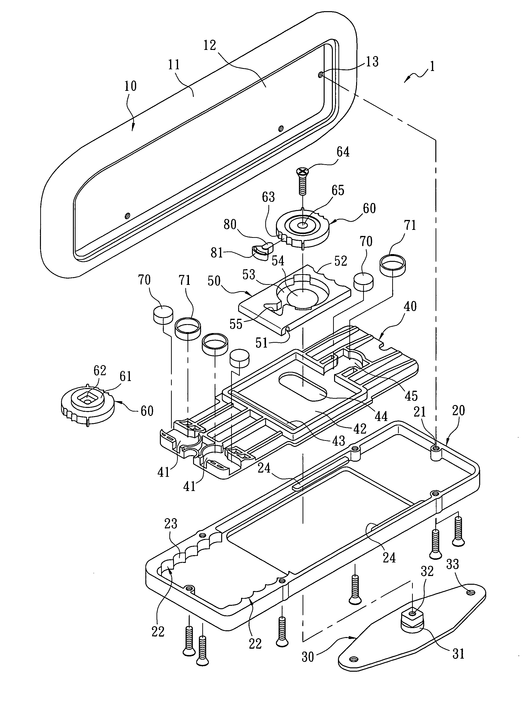
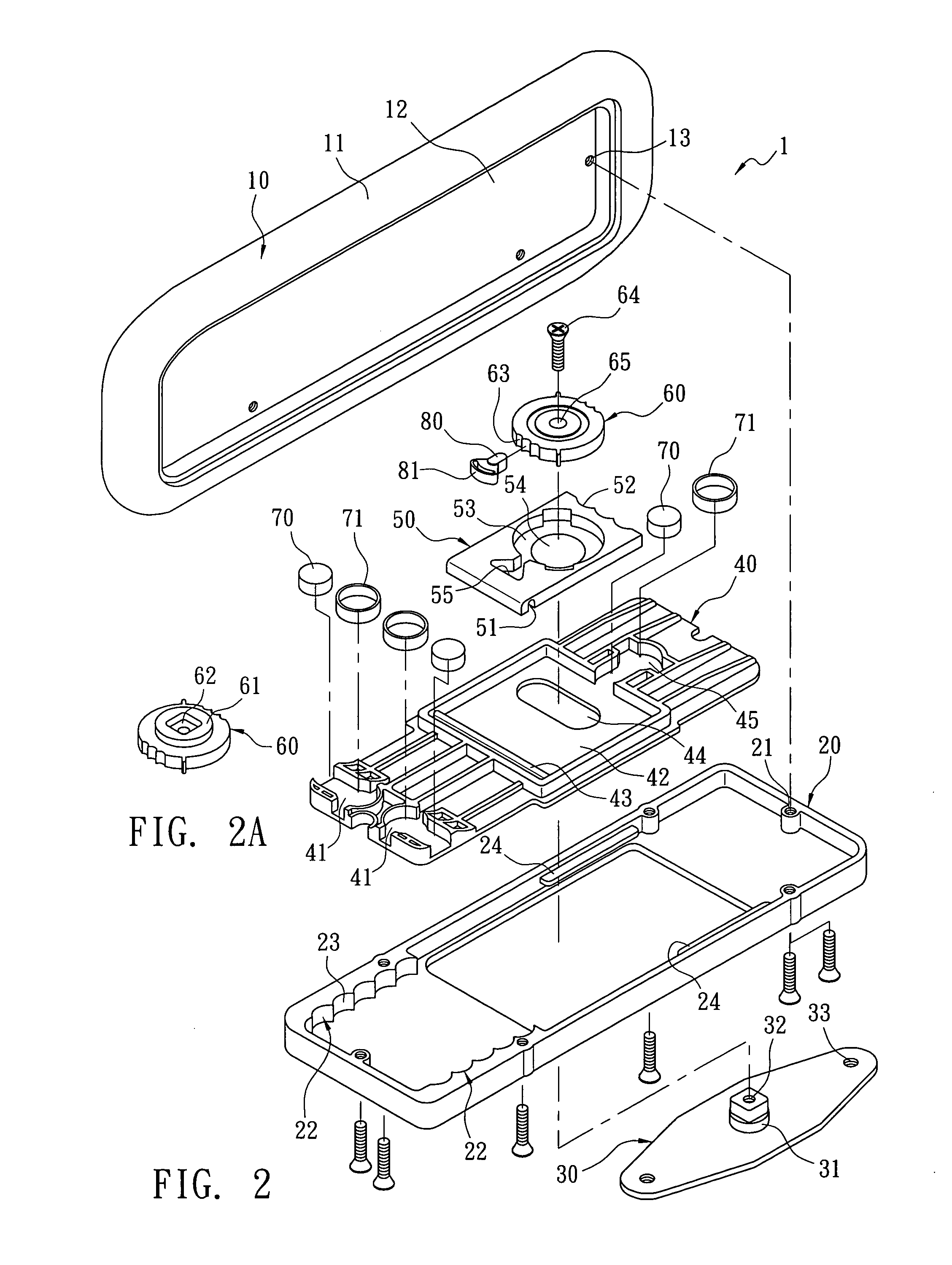
[0003]Therefore it is a primary object of the present invention to provide an adjustment mechanism for armrests that includes a removable block with shorter width disposed under a lower plate of the armrest. The removable block moves forwards and backwards, relative to the lower plate. A rectangular slot with a rectangular piece whose width is smaller than that of the rectangular slot is mounted on the removable block. The rectangular piece and the rectangular slot move transversely, relative to each other. Moreover, a round slot with a disc therein is arranged on the rectangular piece. The rectangular piece and the disc move relative to each other. The center of the disc is secured on a base that is fastened on an armrest support. Thereby the armrest has adjustable rotation angle, longitudinal displacement and transverse displacement.

Problems solved by technology

Although there are various adjustment mechanisms available now, an adjustment mechanism with simple structure and multiple functions of adjusting horizontal positions or angle is rare.

Method used


Image

  • Adjustment mechanism for armrest
  • Adjustment mechanism for armrest
  • Adjustment mechanism for armrest

Examples


Embodiment Construction

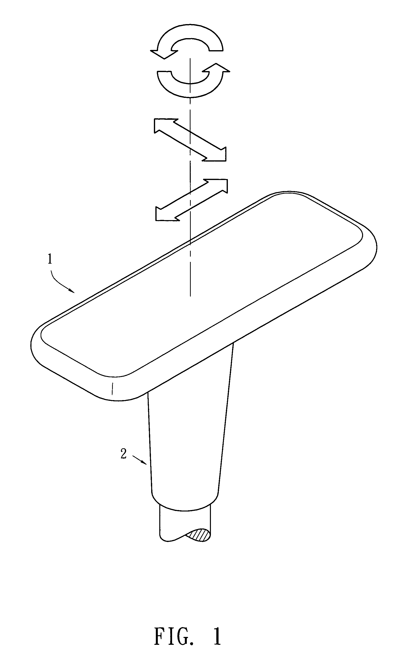
[0012]Refer from FIG. 1 to FIG. 3, an armrest 1 of the present invention secured on top surface of an armrest support 2 consists of an armrest plane 10, a lower plate 20, a base 30, a removable block 40, a rectangular piece 50, a disc 60, a locating ring 70 as well as corresponding elastic member 71, a locating pin 80 and corresponding elastic member 81. The armrest plane 10 is composed by a soft pad layer 11 integrated with a hard plate layer 12. The soft pad layer 11 is made from plastic, rubber, or sponge for providing users good feelings of touch while the hard plate layer 12 is formed by iron or plastic and having a plurality of tapped holes 13 for being assembled with corresponding tapped holes 21 on the lower plate 20. The lower plate 20 is a plastic housing, screwed with the hard plate layer 12 so as to form a rectangular space 25 between the armrest plane 10 and the lower plate 20 for accommodation of adjustment members.

[0013]Two linear locating slots 22 having a plurality ...


PUM


Abstract

An adjustment mechanism for armrests includes an armrest plane and a lower plate fastened under the armrest plane. A removable block with smaller length is disposed inside the lower plate. Elastic locating rings are disposed on right and left sides of the removable lock, corresponding to linear locating slot composed of a plurality of curved slots on right and left sides of an inner part of the lower plate. Thus the removable block and the lower plate are moving or located relative to each other. A rectangular slot with a rectangular piece whose width is smaller than that of the rectangular slot is mounted on the removable block. And curved slots for location is arranged on side of the rectangular piece so that the rectangular piece and the rectangular slot move transversely and being located, relative to each other. Moreover, a round slot with a disc therein is arranged on the rectangular piece while a plurality of locating slots is mounted on circumference of the disc so that the rectangular piece and the disc rotate and locate relative to each other. By a fastening member inserting through the disc, the rectangular piece, and the transverse slot on bottom of the removable block, the disc is secured on a fastening seat that is secured on the armrest support. Thereby the armrest has adjustable rotation angle, longitudinal displacement and transverse displacement, relative to the armrest support.

Description

BACKGROUND OF THE INVENTION[0001]The present invention relates to an adjustment mechanism for armrests, especially to an armrest with adjustable width and rotation angles.[0002]Generally, common seat armrests consist of two parts-armrests and supports. The armrests are disposed on top of the supports while the supports are secured firmly on right and left sides of seats by screws or other means. Traditional office chairs often have several adjustments: armrest height and level adjustment. The level adjustment mechanism for adjusting horizontal position or angles generally is arranged on the armrests. Although there are various adjustment mechanisms available now, an adjustment mechanism with simple structure and multiple functions of adjusting horizontal positions or angle is rare. The present invention provides such kind of design.SUMMARY OF THE INVENTION[0003]Therefore it is a primary object of the present invention to provide an adjustment mechanism for armrests that includes a r...

Claims


Application Information

Patent Timeline
Patent Type & Authority Patents(United States)
IPC IPC(8): A47C7/54
CPCA47C1/03A47C1/0307A47C1/0308
Inventor LEE, HWANG-PAO
Owner ISOTECH PRODS
Learn More