
Control apparatus and method for internal combustion engine

a control apparatus and internal combustion engine technology, applied in mechanical equipment, electric control, machines/engines, etc., can solve the problems of long state and insufficient intake air for a period of time, and achieve the effect of promoting catalyst warming and relatively short tim

Inactive Publication Date: 2007-01-09
TOYOTA JIDOSHA KK
View PDF5 Cites 61 Cited by
  • Summary
  • Abstract
  • Description
  • Claims
  • Application Information

AI Technical Summary

Benefits of technology

The invention provides a control apparatus for an internal combustion engine that improves startability when starting the engine in cold temperatures. The control apparatus includes a variable valve mechanism that can change the lift of the intake valve to improve fuel atomization and promote quicker ignition. The lift of the intake valve is set to a small value when starting the engine, and then increased to a larger value to supply more air to the combustion chamber and improve engine performance. The control apparatus also includes a determining device that monitors engine rotational speed to determine the combustion state of the engine. The lift of the intake valve is maintained at the small value until the engine reaches the initial combustion state, and then increased to the larger value to promote quicker ignition and stable combustion. The control apparatus can improve startability of the internal combustion engine and maintain it in a stable state.

Problems solved by technology

With this apparatus, however, the following problem may occur concerning further improvement of startability.
However, in the state where the lift amount and the working angle are controlled to be small, a sufficient amount of intake air may not be obtained in a period until the internal combustion engine is shifted to a perfect combustion state, namely, a period until the internal combustion engine is shifted to a state where the internal combustion engine can operate by itself.
Accordingly, the period from when the internal combustion engine is shifted to the initial combustion state until when the internal combustion engine is shifted to the perfect combustion state may be long due to an insufficient output from the engine.

Method used


Image

  • Control apparatus and method for internal combustion engine
  • Control apparatus and method for internal combustion engine
  • Control apparatus and method for internal combustion engine

Examples


Embodiment Construction

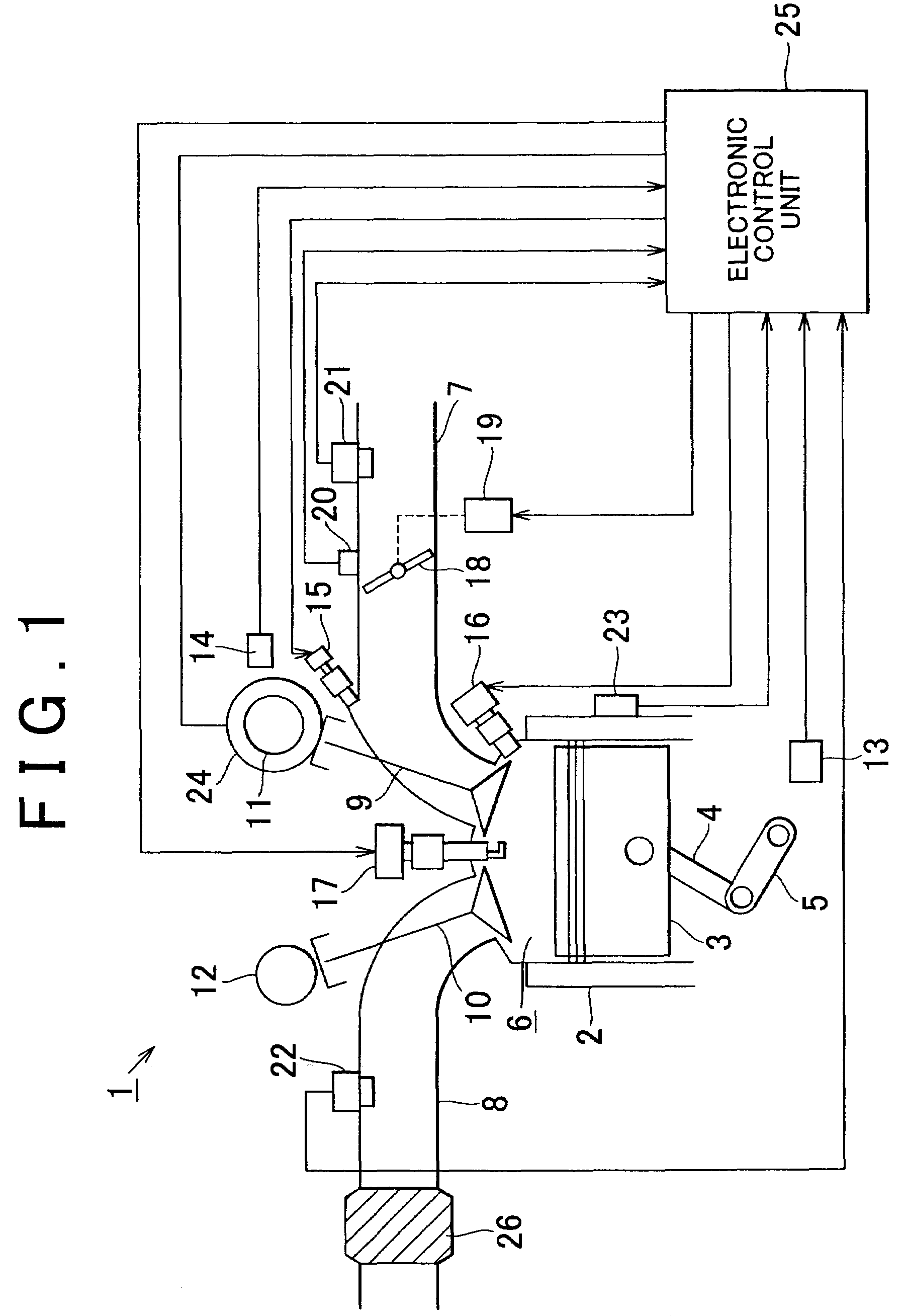
[0033]Hereafter, a control apparatus for an internal combustion engine according to an embodiment of the invention will be described with reference to FIGS. 1, 2, 3A, 3B, and 3C.

[0034]FIG. 1 is a view schematically showing a structure of an internal combustion engine 1. The internal combustion engine 1 is mounted in a vehicle, for example, as a power source for the vehicle. The internal combustion engine 1 includes multiple cylinders 2 (only one of the multiple cylinders 2 is shown in FIG. 1), and a piston 3 is housed in each of the cylinders 2 such that the piston 3 can reciprocate in the cylinder 2. The piston 3 is connected to a crankshaft 5 serving as an output shaft of the internal combustion engine 1 via a connecting rod 4. Reciprocation of the piston 3 is converted into a rotational movement by the connecting rod 4, and then transmitted to the crankshaft 5.

[0035]A combustion chamber 6 of each cylinder 2 is connected to an intake passage 7 through which air is supplied to the ...


PUM


Abstract

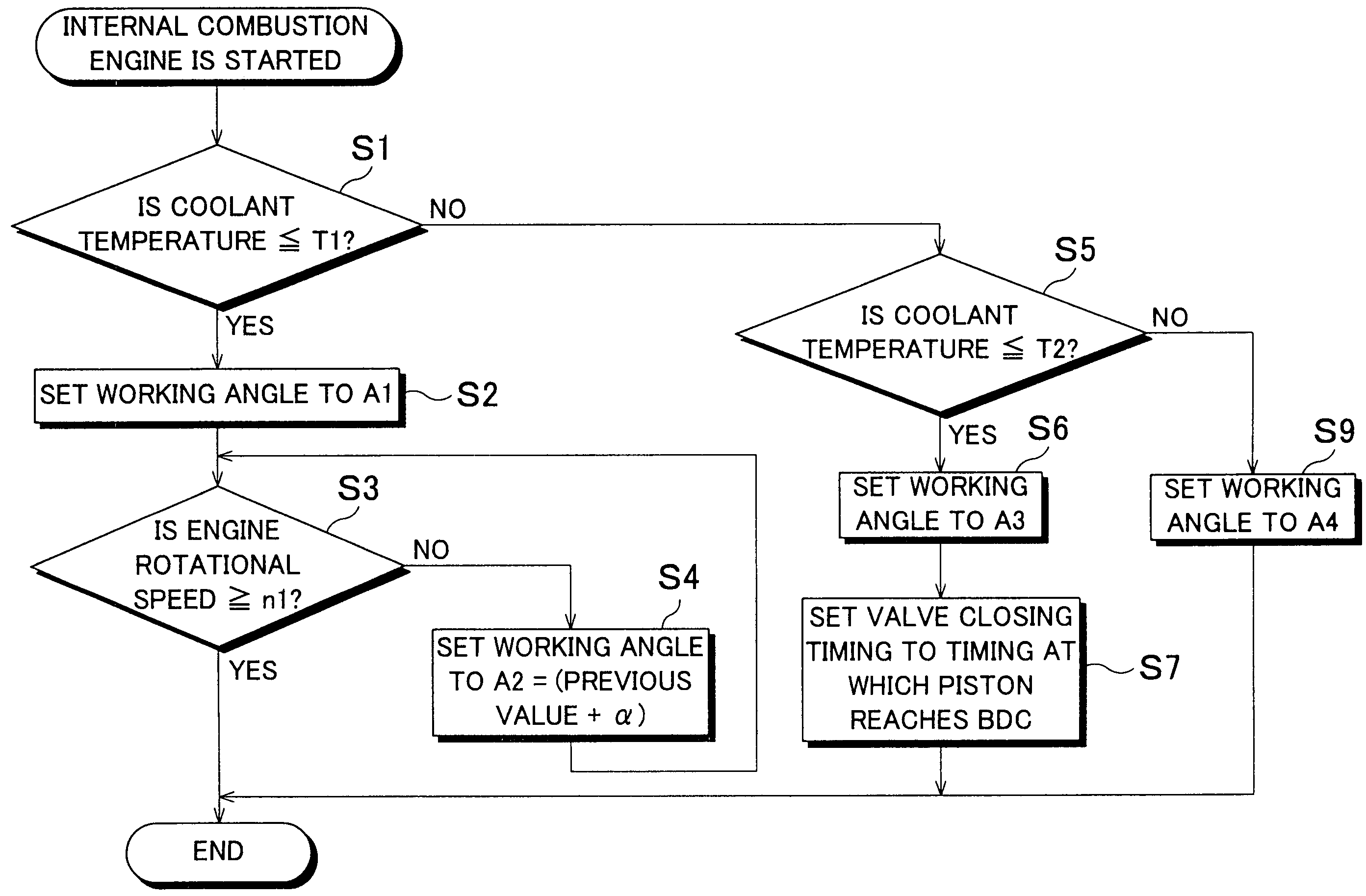
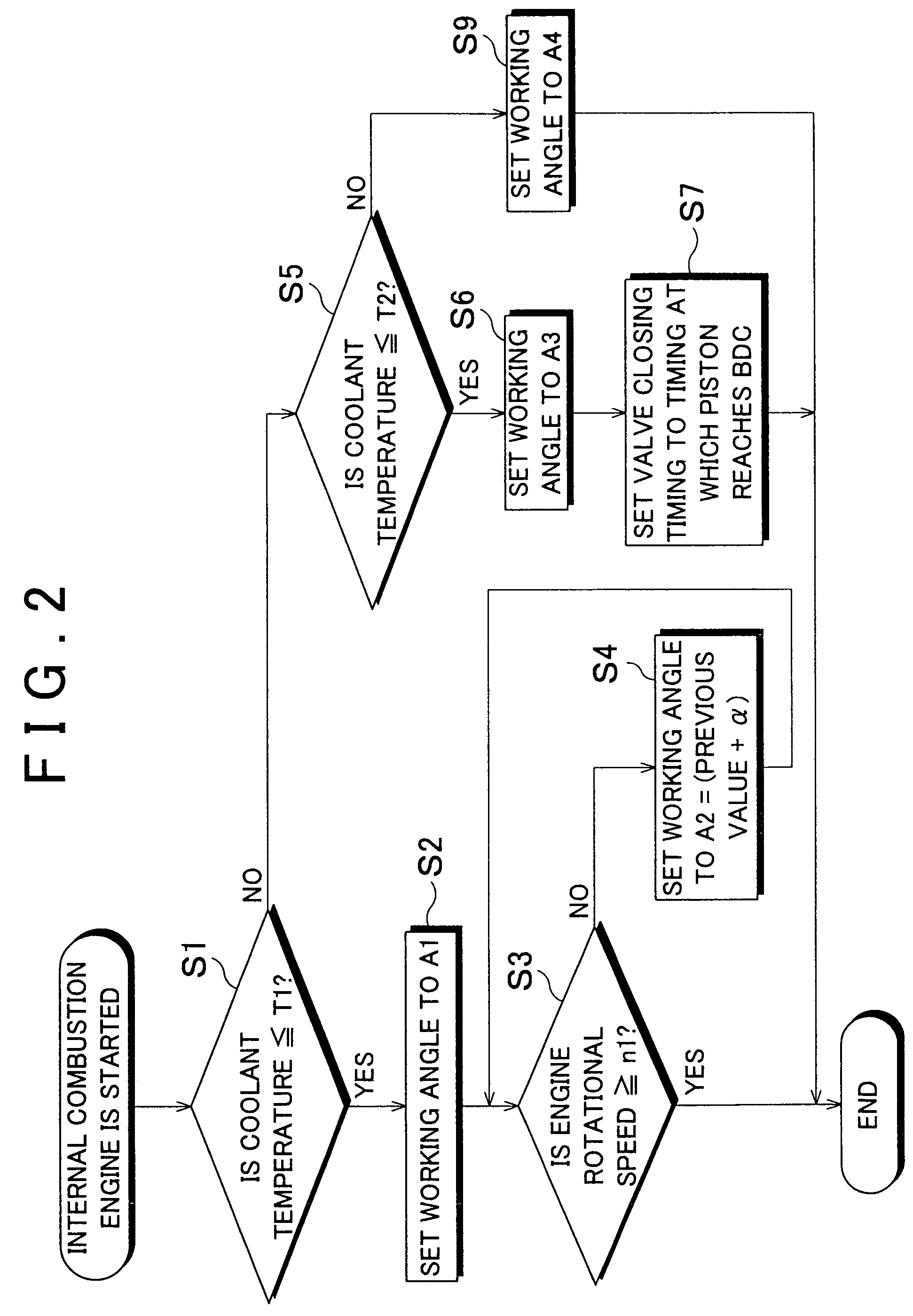
A working angle (lift amount) of an intake valve is set to a predetermined first set value A1 during a period from when starting of the engine is initiated until when the engine is shifted to an initial combustion state, and the working angle is changed to a second set value A2 (=previous value (initial value is A1)+α) that is larger than the first set value A1 during a period from when the engine is shifted to the initial combustion state until when the engine is shifted to a perfect combustion state. When an engine rotational speed becomes equal to or higher than a reference rotational speed n1, it is determined that the engine has been shifted to the perfect combustion state, after which an engine starting routine ends.

Description

INCORPORATION BY REFERENCE[0001]The disclosure of Japanese Patent Application No. 2004-262755 filed on Sep. 9, 2004 including the specification, drawings and abstract is incorporated herein by reference in its entirety.BACKGROUND OF THE INVENTION[0002]1. Field of the Invention[0003]The invention relates to a control apparatus and method for an internal combustion engine including a variable valve mechanism which can change at least a lift amount of an intake valve as an opening / closing characteristic of the intake valve.[0004]2. Description of the Related Art[0005]In an internal combustion engine, an intake air amount required when the internal combustion engine is started (a required air amount) varies depending on an engine operating state such as a temperature of the engine. Conventionally, such a required air amount is adjusted by controlling an opening amount of a throttle valve. However, in recent years, various methods for adjusting the required air amount have been proposed,...

Claims


Application Information

Patent Timeline
Patent Type & Authority Patents(United States)
IPC IPC(8): F02D41/06F01L13/00
CPCF01L13/0015F01L13/00
Inventor YOSHIHARA, MASATOMO
Owner TOYOTA JIDOSHA KK
Learn More