Inductive sensor (speed sensor) with a conical coil base body

a technology of inductive sensor and conical coil, which is applied in the direction of linear/angular speed measurement, instruments, devices using electric/magnetic means, etc., can solve the problems of coil wire breakage, reduce the number of windings, increase the mechanical resistance of the wound coil, and reduce the winding time

Inactive Publication Date: 2007-01-02
ROBERT BOSCH GMBH
View PDF20 Cites 5 Cited by
  • Summary
  • Abstract
  • Description
  • Claims
  • Application Information

AI Technical Summary

Benefits of technology

[0009]In contrast, the inductive sensor according to the invention has the advantage that the coil base body is designed entirely in the shape of a cone. Due to the conical shape of the coil base body, there is no need to provide coil base channels. In particular, this can prevent the coil wire from becoming damaged at the coil base channels during winding or extrusion coating of the coil, which eventually leads to a break in the coil wire if frequent temperature changes occur. Moreover, this can result in an increase in the mechanical resistant of the wound coil to the extrusion-coating pressure, since the coil has a cylindrical or only slightly conical outer circumference after winding. As a further advantage, the provision of the conical coil base body can reduce the number of windings, because there is no need to fill a cylindrical zone having a small diameter, as in the related art. Likewise, there is no need for the costly, complicated procedure of placing the wire in the coil base channels. This reduces the winding time, so that the inductive sensor according to the invention can be produced cost-effectively. It is also possible according to the invention to linearize the ohmic resistance per winding R(n), which results in an increased consistency of resistance. Furthermore, using the inductive sensor according to the invention, more than 1750 temperature changes are achieved in a thermal shock test between −30° C. and +100° C.
[0010]The angle of the exterior circumference of the conical coil base body to a center line of the inductive sensor is preferably approximately 2.85° C. Due to this slightly conical coil base body, it is ensured in particular that the winding wire does not ascend in the direction of the larger diameter of the cone. In particular, this also prevents the winding wire from snarling. The consistency of resistance can be increased as a result, and the number of reject parts can be reduced significantly.
[0011]In a preferred embodiment of the present invention, the windings of the coil on the coil base body are arranged in parallel. As a result, a defined design of the coil can be achieved using the windings. The windings of the coil are thereby preferably arranged in parallel from a first coil shield to a second coil shield, i.e., one winding next to the other one.
[0012]An extrusion coating of the coil is preferably produced out of the same material as the coil base body. As a result, it can be ensured that tensions resulting from different expansion and compression do not damage the wire in the channels of the contact rails to the winding and vice versa. The plastic PA6.12 is hereby 23 preferably used as the material.
[0013]As one can see in FIGS. 1 and 4, the pole core 3 is designed conical in shape and has sections with different diameter. The wall of the coil body, in particular of the coil base body, facing the pole core 3 corresponds with the shape of the pole core for reasons of space. As one can see by comparing FIGS. 1 and 4, the slightly conical shape means a thicker formation of the wall of the coil base body. More material is required to create the slightly conical shape. This would increase the size while maintaining the same coil ratios as in the related art. The advantageous shape of the coil base body results in a more harmonic distribution of the windings, however. The “density” of the winding based on the length and volume of the coil base body is increased. A smaller number of windings is used to achieve the same performance as with the related art, without resulting in a taller design than with the related art. It is also particularly advantageous that the ohmic resistance remains constant within a series.

Problems solved by technology

In particular, this can prevent the coil wire from becoming damaged at the coil base channels during winding or extrusion coating of the coil, which eventually leads to a break in the coil wire if frequent temperature changes occur.

Method used


Image

  • Inductive sensor (speed sensor) with a conical coil base body
  • Inductive sensor (speed sensor) with a conical coil base body
  • Inductive sensor (speed sensor) with a conical coil base body

Examples


Embodiment Construction

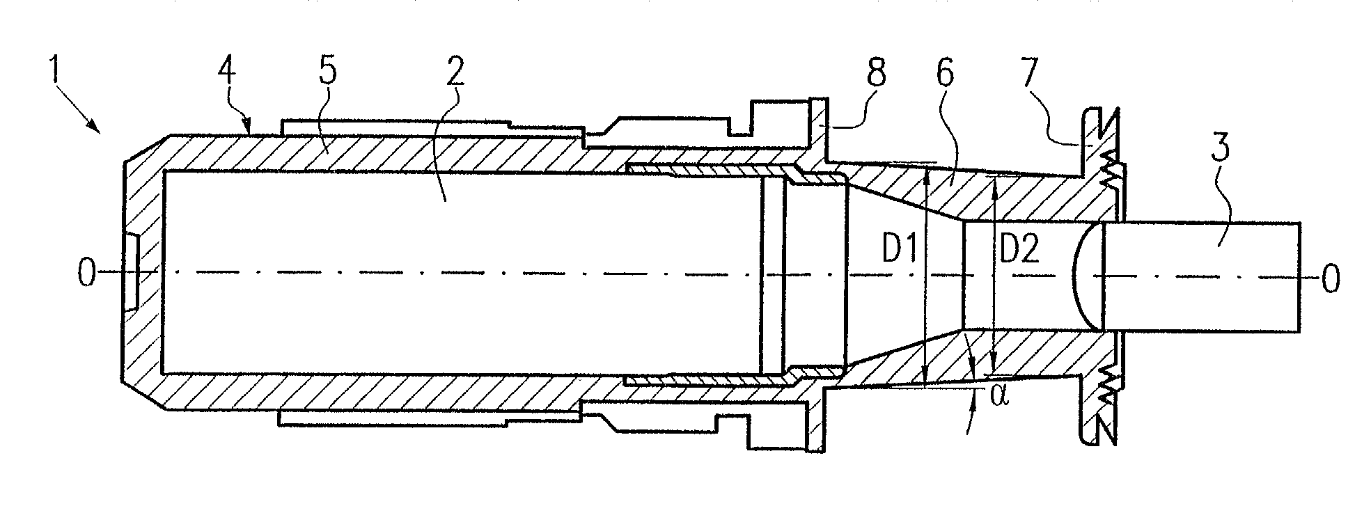
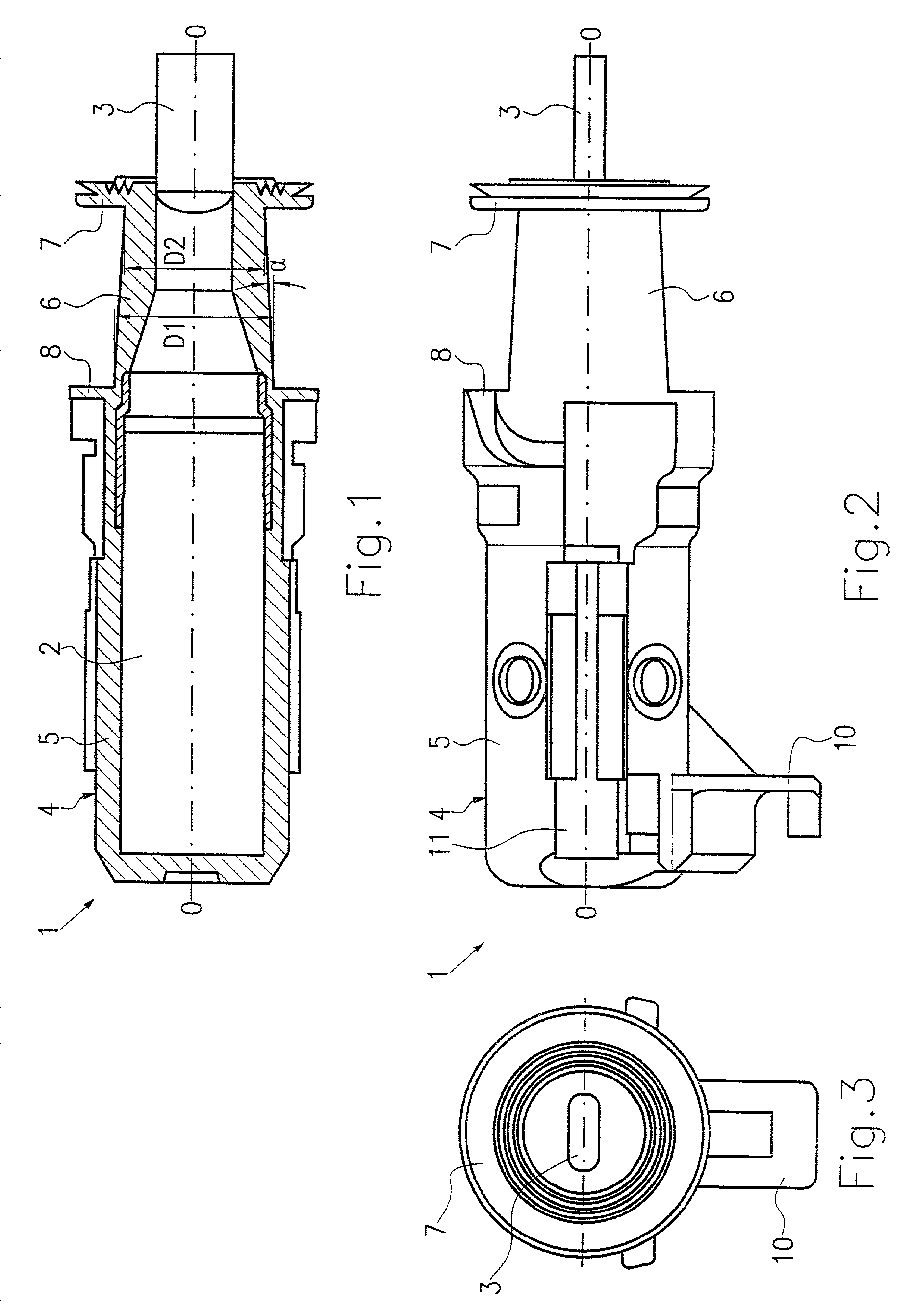
[0020]An embodiment of an inductive sensor according to the present invention is shown in FIGS. 1 through 3. As shown in FIG. 1 in particular, the inductive sensor 1 comprises a magnet 2 produced out of AlNiCo with a pole pin 3 situated on one end.

[0021]The magnet 2 is completely surrounded by a housing 4 produced out of plastic, whereby the pole pin 3 projects out of the housing 4. The housing 4 is designed as a single part and comprises a main housing body 5 and a coil base body 6. Moreover, a first coil shield 7 and a second coil shield 8 are also designed as a single part with the housing 4. Polyamide PA6.12, for example, can be used as the material for the housing.

[0022]As shown in FIGS. 1 and 2, the coil base body 6 is situated between the first coil shield 7 and the second coil shield 8. The coil base body 6 is hereby designed in a slightly conical shape, whereby the larger diameter D1 of the cone of the coil base body 6 is situated at the second coil shield 8, and the smalle...


PUM


Abstract

In summary, the present invention concerns an inductive sensor, in particular rpm sensor, having a housing (4) with a main housing body (5) and a coil base body (6), whereby a coil is wound around the coil base body (6). The sensor also comprises a magnet (2) that is situated in the housing and has a pole pin (3). The coil base body (6) of the housing (4) is thereby designed entirely conical, in particular slightly conical, in shape.

Description

BACKGROUND OF THE INVENTION[0001]The present invention concerns an inductive sensor, in particular rpm sensor.[0002]Inductive sensors are used, for example, to detect the rpm's of a vehicle wheel as an rpm sensor for antilock systems. This is a passive inductive sensor, the function of which is based on the principle of electromagnetic induction. A ferromagnetic pulse wheel permanently mounted on the wheel axle induces a voltage that is a function of the rpm's in a coil of the sensor attached at a constant distance in that it changes the direction of the magnetic field over the rising and falling flanks of the teeth of the pulse wheel. A sensor of this type is shown in FIGS. 4 and 5. An inductive sensor of this type comprises a housing 4 in which a permanent magnet 2 having a pole pin 3 is situated. The magnet 2 comprises a ferrite core (AlNiCo) and a cold-formed pole core to conduct and bundle the magnetic lines of force. As shown in FIG. 4, the cold-formed pole core is designed pa...

Claims


Application Information

Patent Timeline
Patent Type & Authority Patents(United States)
IPC IPC(8): G01B7/14G01P3/44G01D5/245G01P1/02G01P1/04G01P3/488
CPCG01P1/02G01P3/488G01P1/04
Inventor JENNERJAHN, ANDREAS
Owner ROBERT BOSCH GMBH
Why Eureka
Try Eureka