
Expandable structures for deployment in interior body regions

a technology of expanding structures and interior body regions, applied in the field of expanding structures, can solve the problems of still being difficult to gain access along the natural axis of symmetry, and the optimization of conventional structures is problemati

Inactive Publication Date: 2007-01-02
ORTHOPHOENIX
View PDF20 Cites 135 Cited by
  • Summary
  • Abstract
  • Description
  • Claims
  • Application Information

AI Technical Summary

Benefits of technology

"The invention provides a device for deployment in interior body regions that includes an outer catheter tube, an inner catheter tube, and an expandable structure. The expandable structure has double-jointed end regions that provide a maximum diameter along the entire length of the structure. The device can be manufactured by bonding the inner and outer catheter tubes and the expandable structure using an adhesive or melt bonding process. The device can be secured against further movement by an adhesive process. The technical effect of the invention is to provide a device that can be easily deployed in interior body regions and provide a maximum diameter for the treatment of targeted areas."

Problems solved by technology

Even if an interior body region is somewhat more symmetric, it may still be difficult to gain access along the natural axis of symmetry.
Indeed, the larger the balloon diameter, the longer the end cone, which creates a tradeoff between maximum effective length and maximum effective diameter.
This tradeoff makes optimization of conventional structures problematic in interior structures with defined lengths, such as bone.

Method used


Image

  • Expandable structures for deployment in interior body regions
  • Expandable structures for deployment in interior body regions
  • Expandable structures for deployment in interior body regions

Examples


Embodiment Construction

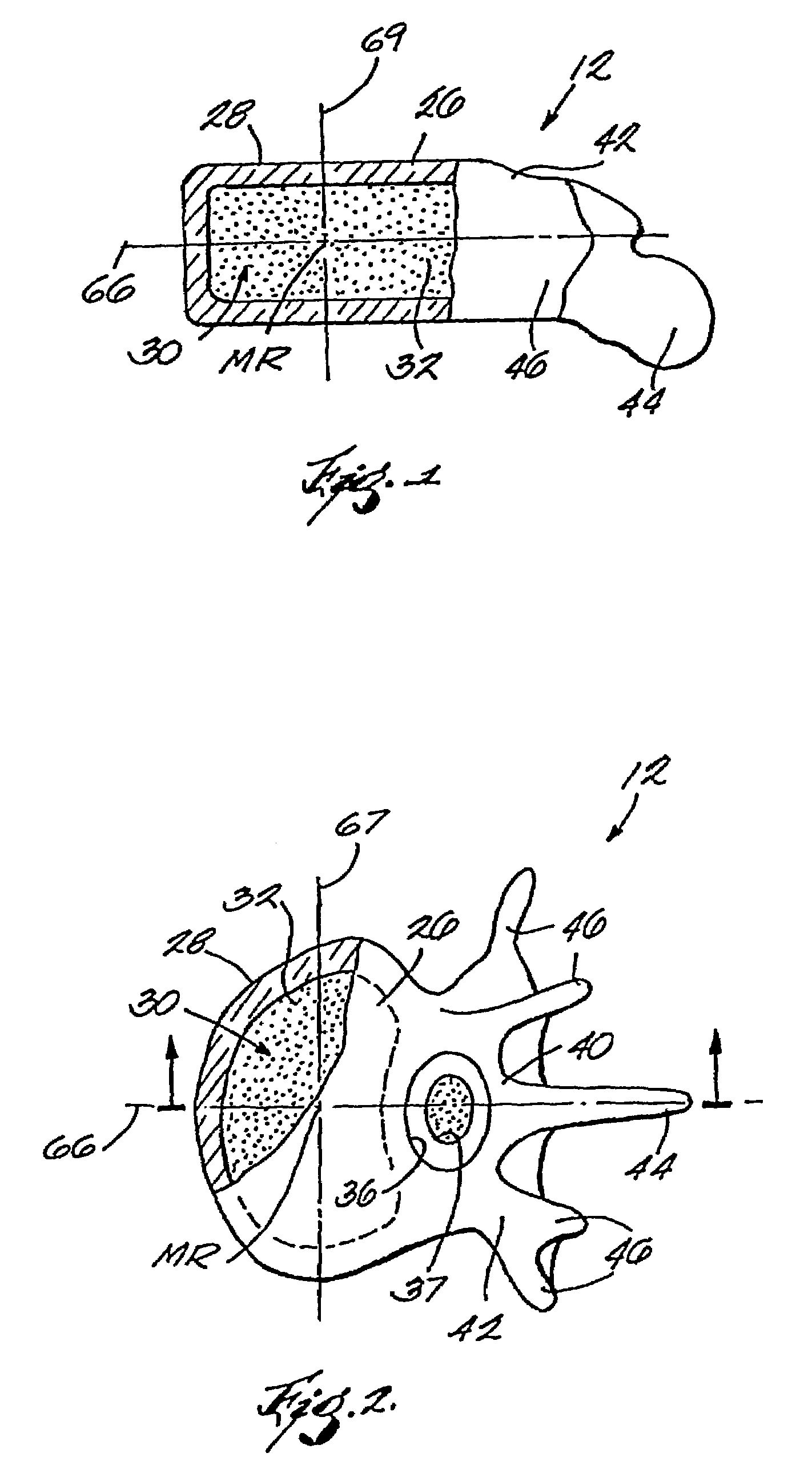
[0045]The preferred embodiment first describes improved systems and methods that embody features of the invention in the context of treating bones. This is because the new systems and methods are advantageous when used for this purpose.

[0046]Another preferred embodiment describes the improved systems and methods in the context of relieving constrictions or blockages within branched blood vessels. This is because the vasculature also presents an environment well suited to receive the benefits of the invention.

[0047]The two environments are described for the purpose of illustration. However, it should be appreciated that the systems and methods as described are not limited to use in the treatment of bones or the vasculature. The systems and methods embodying the invention can be used virtually in any interior body region that presents an asymmetric geometry, or otherwise requires an access path that is not aligned with the natural axis of the region.

I. Deployment in Bones

[0048]The new...


PUM

PropertyMeasurementUnit
lengthaaaaaaaaaa
ultimate elongationaaaaaaaaaa
pressuresaaaaaaaaaa

Abstract

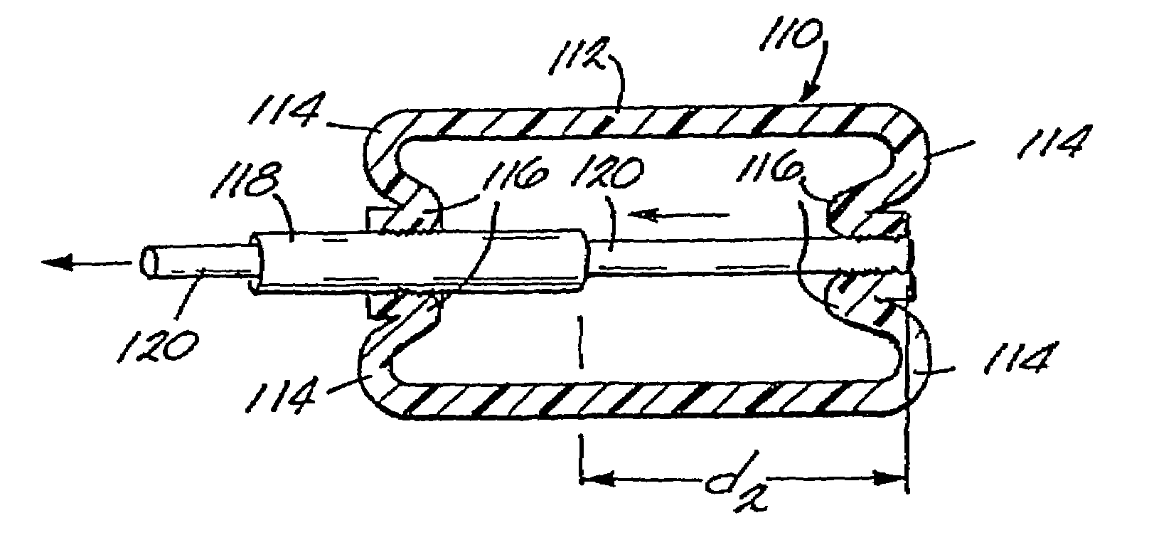
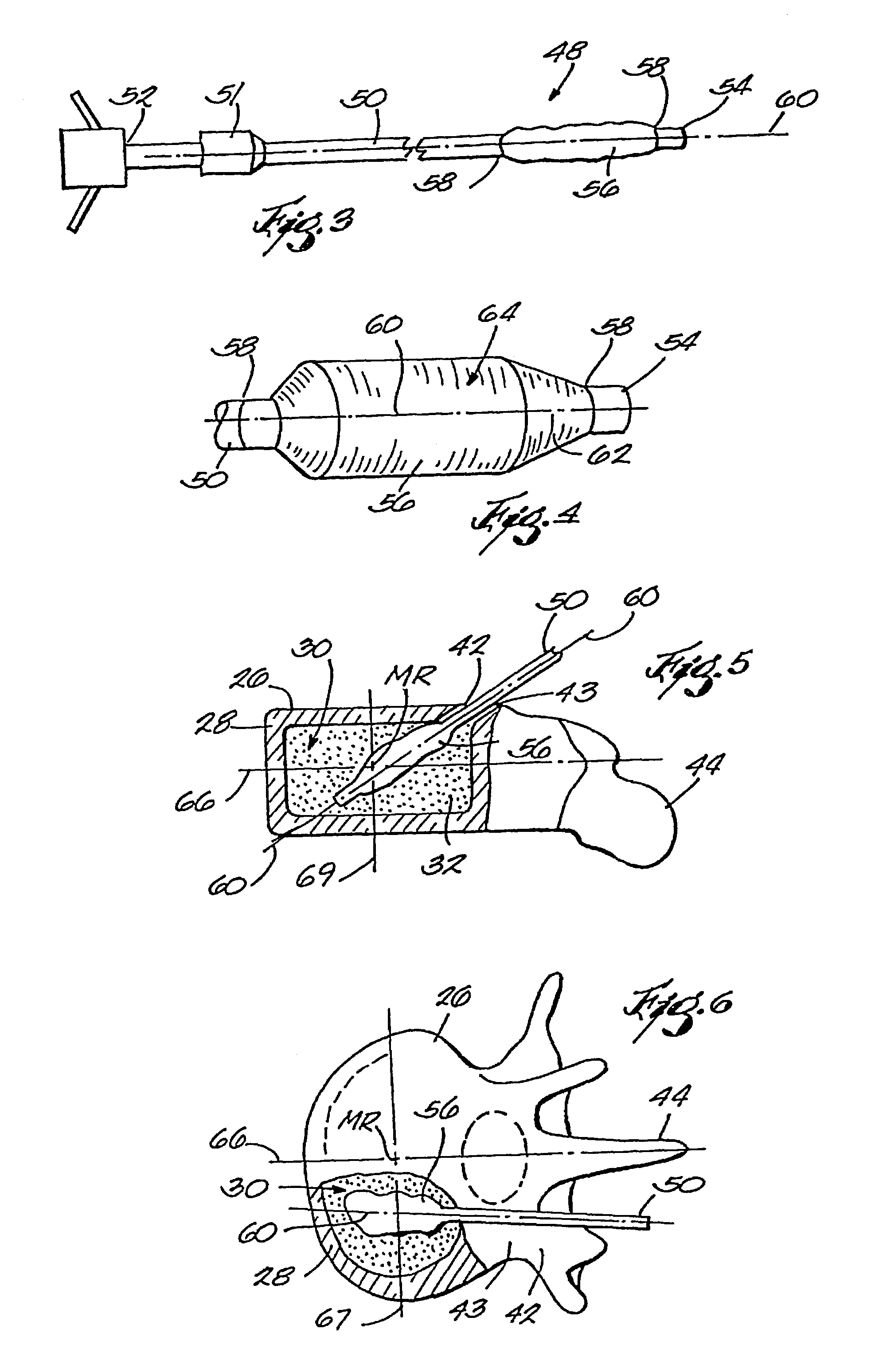
Apparatus for deploying an expandable structure in interior body regions provide an outer catheter tube, an inner catheter tube sized and configured to be received within the outer catheter tube, and an expandable structure having a distal end and a proximal end. The expandable structure also has a first end region adjacent the distal end and a second end region adjacent the proximal end. The distal end is bonded to the inner catheter tube to form a first bonded region and the proximal end is bonded to the outer catheter tube to form a second bonded region. The first end region is inverted to overlie the first bonded region and the second end region is inverted to overlie the second bonded region.

Description

RELATED APPLICATIONS[0001]This application is a divisional U.S. patent application Ser. No. 09 / 918,942 filed Jul. 31, 2001 now U.S. Pat. No. 6,623,505, which is a divisional of U.S. patent application Ser. No. 09 / 404,662, filed Sep. 23, 1999, now U.S. Pat. No. 6,280,456, which is a divisional of U.S. patent application Ser. No. 08 / 911,827, filed Aug. 15, 1997, now U.S. Pat. No. 5,972,015.FIELD OF THE INVENTION[0002]The invention relates to expandable structures, which, in use, are deployed in interior body regions of humans and other animals.BACKGROUND OF THE INVENTION[0003]The deployment of expandable structures into interior body regions is well known. For example, expandable structures, generically called “balloons,” are deployed during angioplasty to open occluded blood vessels. As another example, U.S. Pat. Nos. 4,969,888 and 5,108,404 disclose apparatus and methods the use of expandable structures for the fixation of fractures or other osteoporotic and non-osteoporotic conditi...

Claims


Application Information

Patent Timeline
Patent Type & Authority Patents(United States)
IPC IPC(8): A61M29/00A61B10/00A61B10/02A61B17/00A61B17/12A61B17/72A61B17/74A61B17/78A61B17/88A61B19/00A61B19/02A61F2/00A61F2/28A61F2/30A61F2/42A61F2/44A61F2/46
CPCA61B10/025A61B17/1204A61B17/12099A61B17/12109A61B17/12136A61B17/8855A61F2/28A61F2/441A61F2/4601A61F2/4611A61B17/00234A61B17/7258A61B17/7275A61B17/74A61B17/744A61B19/0271A61B19/54A61B2010/0258A61B2017/00539A61B2017/00544A61B2019/0219A61B2019/0286A61B2019/446A61F2/2846A61F2/44A61F2002/2817A61F2002/2825A61F2002/2828A61F2002/2832A61F2002/2835A61F2002/2853A61F2002/2871A61F2002/2892A61F2002/30113A61F2002/30115A61F2002/30125A61F2002/30133A61F2002/30225A61F2002/30228A61F2002/30242A61F2002/30247A61F2002/30253A61F2002/30285A61F2002/30288A61F2002/30308A61F2002/30311A61F2002/30313A61F2002/30448A61F2002/30462A61F2002/30464A61F2002/30581A61F2002/30586A61F2002/30599A61F2002/30677A61F2002/30909A61F2002/4217A61F2002/4602A61F2002/4627A61F2002/4635A61F2002/4636A61F2002/4685A61F2220/005A61F2220/0075A61F2230/0006A61F2230/0008A61F2230/0015A61F2230/0063A61F2230/0065A61F2230/0069A61F2230/0071A61F2230/0076A61F2250/0063A61F2310/00293A61F2310/00353A61F2310/0097A61B50/33A61B90/39A61B90/94A61B2050/0065A61B2050/3015A61F2002/302A61F2002/30245
Inventor SCRIBNER, ROBERT MREO, MICHAEL L
Owner ORTHOPHOENIX
Learn More