
Clutch unit

a technology of clutch and unit, which is applied in the direction of interengaging clutches, electric propulsion mounting, gearing, etc., can solve the problems of large weight, large transmission capacity, and large size of electromagnetic clutches

Inactive Publication Date: 2007-01-02
TOCHIGI FUJI IND CO LTD
View PDF15 Cites 16 Cited by
  • Summary
  • Abstract
  • Description
  • Claims
  • Application Information

AI Technical Summary

Benefits of technology

The solution enhances torque transmitting capacity, suppresses engagement shocks, and maintains a positive engaged state while preventing drag torque, improving fuel efficiency and maintaining driving source durability.

Problems solved by technology

However, in the case of a configuration in which a changeover of transmission and cutoff of torque is effected by the electromagnetic clutch, there is a problem in that the torque transmitting capacity is small.
If an attempt is made to enlarge the torque transmitting capacity of the electromagnetic clutch, the electromagnetic clutch becomes large in size, and there are problems in that the weight becomes large, and that the cost becomes high.
In addition, in the case of the electromagnetic clutch using a multiplicity of friction plates, even if the electromagnetic clutch is set in a cutoff state, there is a possibility of the occurrence of a large drag torque due to the viscosity of oil and the like.
The larger the electromagnetic clutch, the more this drag torque increases, so that an increase in the torque transmitting capacity of the electromagnetic clutch is limited.

Method used


Image

  • Clutch unit
  • Clutch unit
  • Clutch unit

Examples


Embodiment Construction

[0046]The object of suppressing engagement shocks is realized by providing restricting means for restricting the engaging coupling of the dog clutch until the a revolution of the input shaft and a revolution of the output shaft correspond to each other so as to be suitable for engagement.

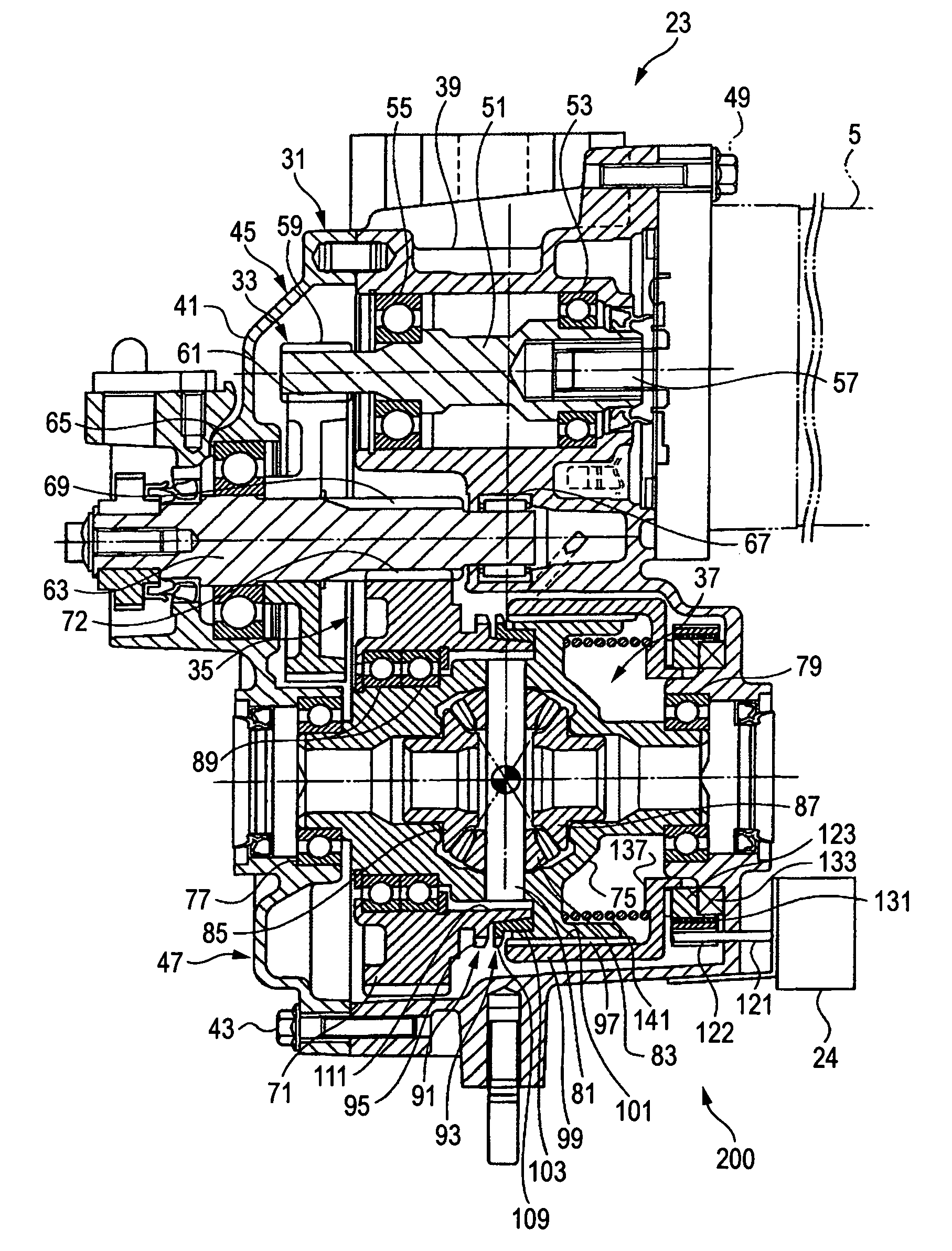
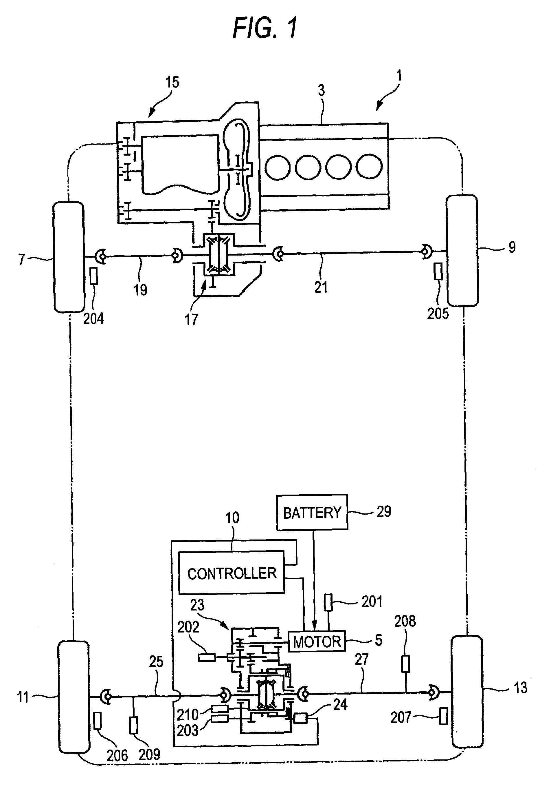
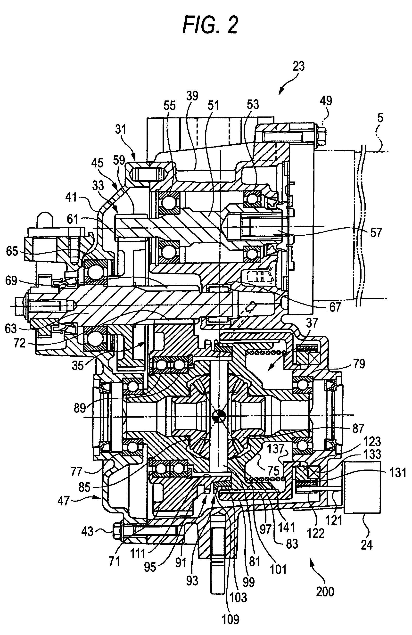
[0047]FIG. 1 is a skeleton plan view of a four-wheel drive vehicle to which a clutch unit of the invention is applied. As shown in FIG. 1, a four-wheel drive vehicle 1 has an engine 3 which is internal combustion engine serving as a main driving source and an electric motor 5 serving as an auxiliary driving source. The engine 3 in this embodiment is a driving source for driving left and right front wheels 7 an 9, while the electric motor 5 is a driving source for driving left and rear wheels 11 and 13 under control by a controller 10. However, a configuration may be provided such that the front wheels are driven by the electric motor 5 which is the auxiliary driving source, and the rear wheels 11 an...


PUM


Abstract

In a clutch unit, an engagement of a dog clutch can be restricted until a revolution of an input shaft and the revolution of an output shaft correspond to each other so as to be suitable for the engagement. The engagement can be effected when the revolution of the input shaft and the revolution of the output shaft have corresponded so as to be suitable for the engagement. Accordingly, the revolution of the input shaft and the revolution of the output shaft are speedily synchronized, and engagement shocks of the dog clutch can be accurately suppressed. Hence, it is possible to reliably transmit the torque to be transmitted from the driving source to the wheel side through the reduction mechanism.

Description

BACKGROUND OF THE INVENTION[0001]The present invention relates to a clutch unit used in a reduction-drive device, and a vehicle having the clutch unit.[0002]An electromagnetic clutch using a multiplicity of friction plates is known as a conventional clutch unit for a differential-drive device. The differential-drive device has a reduction mechanism and a differential (differential device). The electromagnetic clutch is provided between the reduction mechanism and the differential in the differential-drive device, and changeovers a torque transmission and torque cutoff between the reduction mechanism and the differential.[0003]Accordingly, if the electromagnetic clutch is in a torque transmitting state, as the driving source is driven for generating driving torque, the torque which has been decelerate through the reduction mechanism is transmitted to the differential through the electromagnetic clutch. The torque is transmitted from the differential to the left and right axle shafts....

Claims


Application Information

Patent Timeline
Patent Type & Authority Patents(United States)
IPC IPC(8): B60K1/00B60K17/16B60K17/356B60K6/02F16D28/00B60K6/44B60K6/52B60K17/04B60K17/34B60K17/346B60L50/16B60W10/08B60W20/00F16D11/04F16D23/06F16H1/06F16H48/08
CPCF16D23/06B60K6/52B60K17/356Y10T477/79Y02T10/6265Y10T477/26Y02T10/62
Inventor TERAOKA, MASAO
Owner TOCHIGI FUJI IND CO LTD
Learn More